 |
|||
|
|
|||
|
|
|||
| ||||||||||
|
|
 these items with two C-clamps to compress dust shield
given are performed with the transmission installed in the
(6). This will permit entry of the assembly into coupling
truck.
plate (8).
b. Operational test. Operate truck, checking for
(3) Fasten both assemblies to coupling plate (8)
troubles given in transmission part of the trouble-
with screws (10) and install lock wire as required.
shooting chart. Where incorrect pressures might be a
Remove C-clamps.
factor in malfunction, perform pressure tests in c below.
(4) Install items 2, 3, 4, 5 and 6 as shown
c. Testing pressures.
vertically in Figure 6-14, and compress with C-clamps.
(1) To test pressures of hydraulic supply system
(5) Fasten items assembled thus far to stub yoke
of transmission, remove truck floor pan for access and
with screws (1), slide stub yoke, as assembled, forward
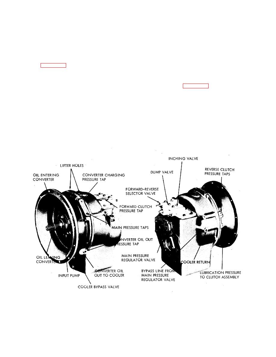
connect pressure gage into CONVERTER CHARGING
to meet handbrake drum of drive axle, and attach drive
PRESSURE port (figure 6-15), start engine and run at
shaft to handbrake drum with screws. Secure with lock
2000 rpm until transmission oil reaches 180 deg to 200
wire and remove C-clamps.
deg F. Gage should read 84 to 101 psi.
6-28. TRANSMISSION.
(2) Connect gage to either MAIN PRESSURE
port. Gage should read 120 to 135 psi.
a. Testing. Testing of the transmission is best done
in two phases, when possible, as given below in this
(3) With inching valve in (brake pedal released),
paragraph. Perform the general operational test to
plug CONVERTER OIL OUT line to cooler. Increase.
determine areas of unsatisfactory performance, then
speed slowly from idle. Gage at COOLER BYPASS
make the pressure tests to isolate the cause of
VALVE port should rise to maximum of 50 to 70 psi.
malfunction to a particular unit, part, or system. Tests
Figure 6-15. Transmission, Showing Pressure Check Points
72
|
|
Privacy Statement - Press Release - Copyright Information. - Contact Us |
