 |
|||
|
|
|||
|
Page Title:
Figure 3-38. Oil pressure transmitter, installed view. |
|
||
| ||||||||||
|
|
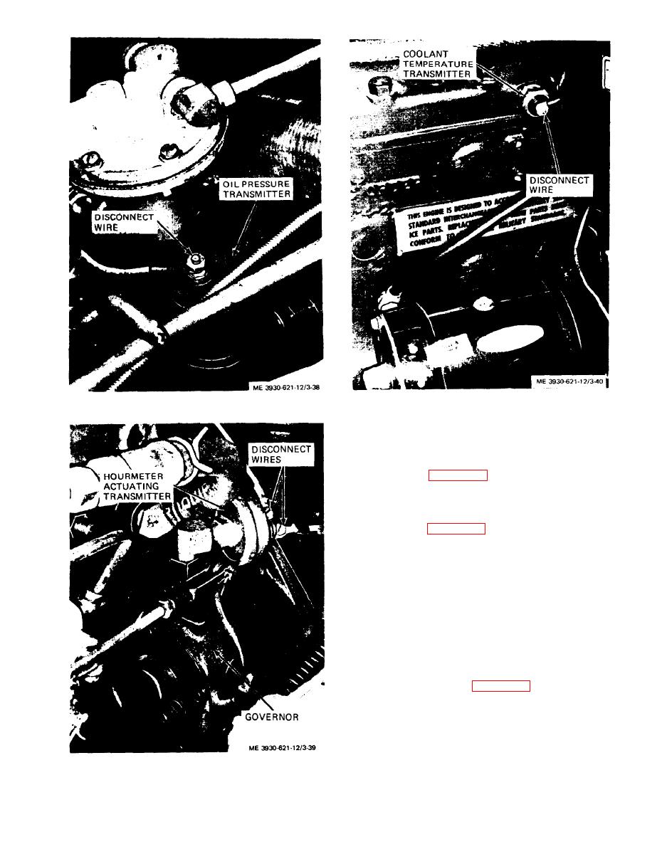 Figure 3-40. Coolant temperature transmitter, installed view.
Figure 3-38. Oil pressure transmitter, installed view.
(2) Refer to figure 3-39 and disconnect two wires
from hourmeter actuating transmitter and remove
transmitter from elbow in top of governor. Install
new transmitter and connect wires.
(3) Refer to figure 3-40 and disconnect wire from
coolant temperature transmitter and remove trans-
mitter from cylinder head. Install new transmitter
and connect wire to terminal.
3-49. Lights
a. General. The lights on the lift truck consist of
either one or two headlights and a stop and taillight.
The headlight is mounted on a bracket on the mast.
The taillight is mounted on the counterweight for-
ward of the radiator cap.
b. Headlight.
lamp from the headlight as follows:
(a) Pull rubber bezel from headlight base.
Loosen the terminal screws and disconnect the wires
from the lamp.
(b) Using care, push the lamp from the bezel.
(c) To remove headlight from truck, disconnect
Figure 3-39. Hourmeter actuating transmitter, installed view.
3-37
|
|
Privacy Statement - Press Release - Copyright Information. - Contact Us |
