 |
|||
|
|
|||
|
Page Title:
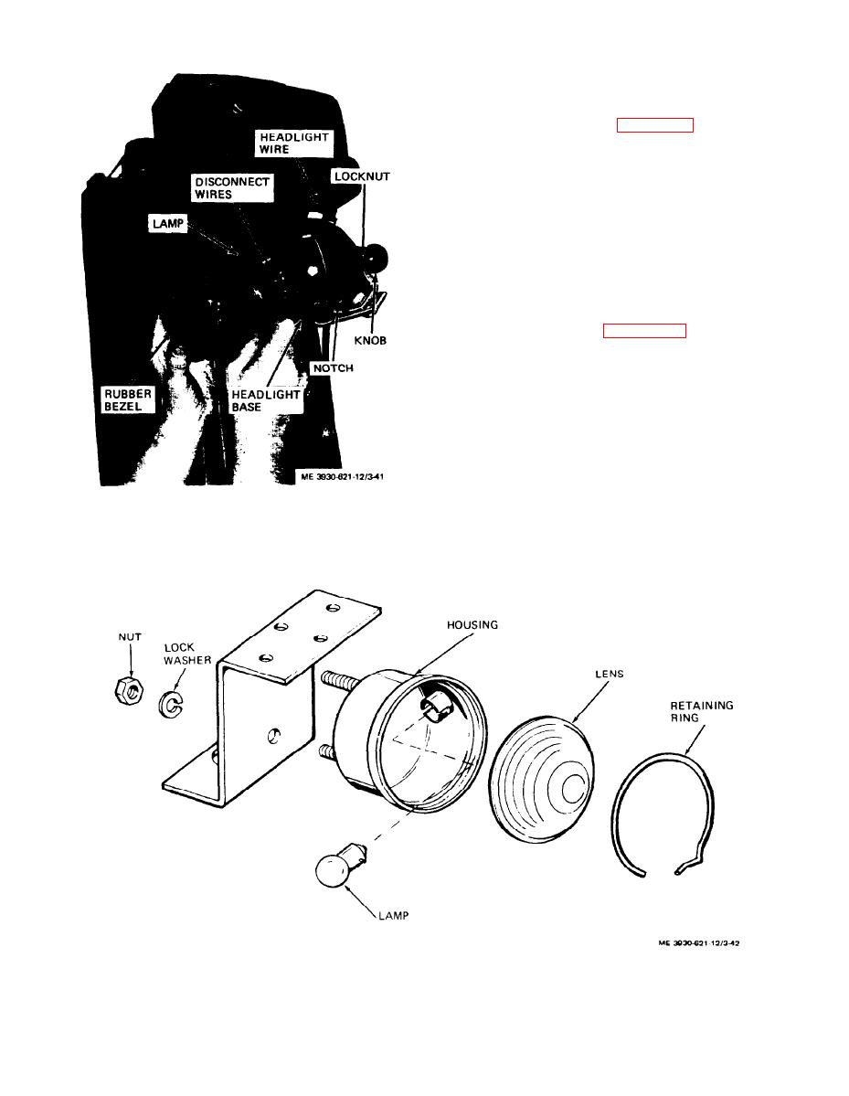
Figure 3-42. Combination rear light, exploded view. |
|
||
| ||||||||||
|
|
 wire from headlight. Unscrew adjusting knob and
remove locknut. Remove the headlight assembly
from the mounting bracket. Remove lamp as de-
scribed above.
the headlight.
(a) Install headlight on bracket and secure
with locknut and adjusting knob. Connect wire to
headlight.
(b) Install lamp in bezel.
(c) Connect wires to lamp terminals and tight-
en screws.
(d) Install bezel and lamp in headlight base.
Aline projections on bezel with notches on base and
press bezel into place.
c. Combination Rear Light.
combination rear light as follows:
(a) Remove lock ring securing lens in lamp.
(b) Depress lamp and turn one-quarter turn
counterclockwise to remove from socket.
(c) Disconnect wires from connectors and re-
move two nuts and washers securing light to bracket
and remove light.
Figure 3-41. Headlight, removal and installation.
Figure 3-42. Combination rear light, exploded view.
3-38
|
|
Privacy Statement - Press Release - Copyright Information. - Contact Us |
