 |
|||
|
|
|||
|
|
|||
| ||||||||||
|
|
 illustrated on figure 3-17. Refer to the illustration to
(5) Stop engine, remove gage and fittings and
remove any of the parts requiring replacement. Do
connect outlet fuel line to pump.
not remove the complete assembly.
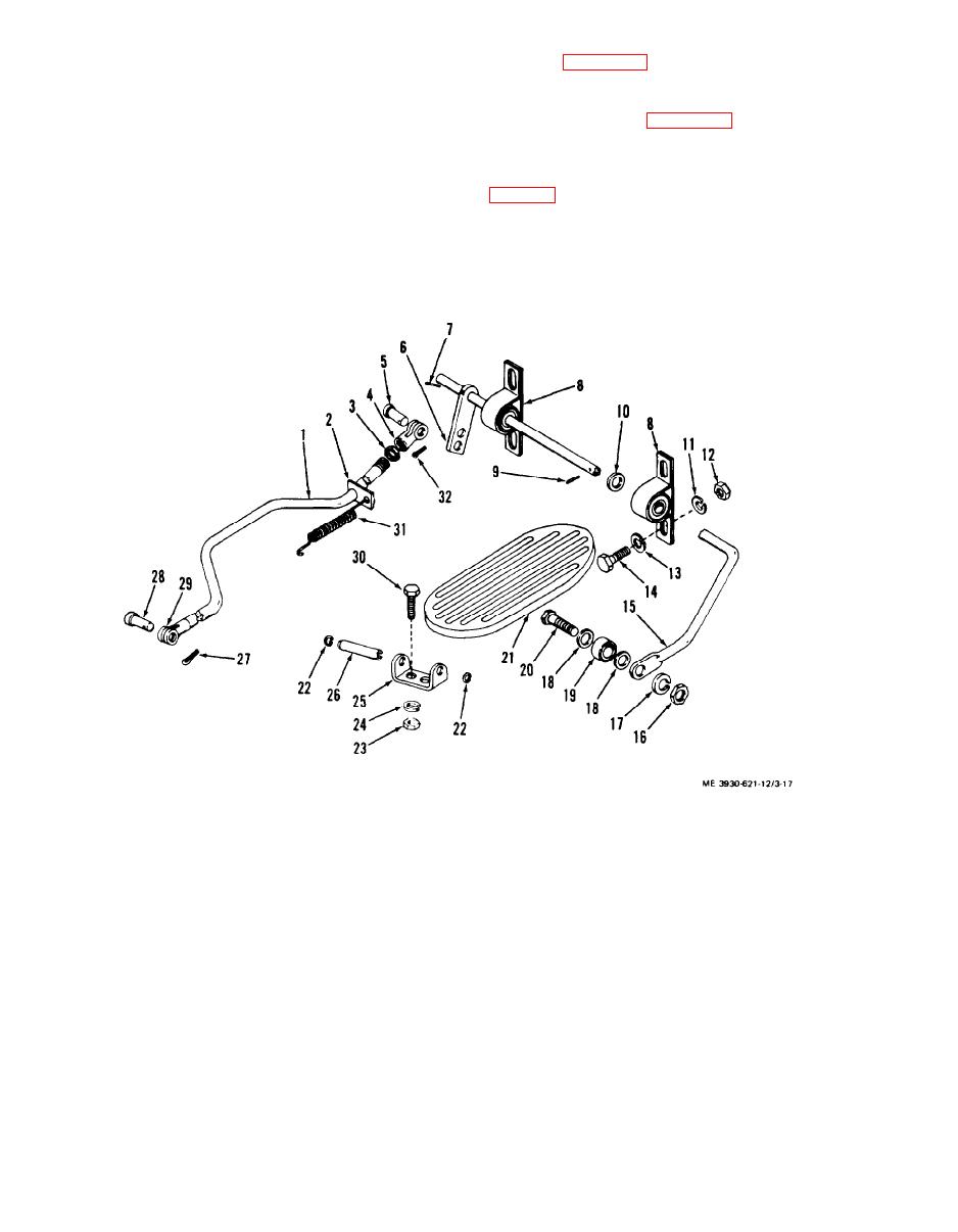
3-32. Accelerator Pedal and Linkage
of the accelerator pedal and linkage removed for
a. General. The accelerator pedal is mounted on
replacement.
the right side of the operator's floor board. Depress-
d. Adjustment. After installing accelerator rod
ing the pedal moves the carburetor throttle lever to
(1, fig. 3-17), adjust clevis (4) to obtain a loose fit on
an open position, increasing engine speed.
the pins.
b. Removal. The accelerator pedal and linkage is
17. Lock washer
1. Accelerator rod
18. Flat washer
2. Clip
19. Bearing
3. Nut
20. Screw
4. Clevis
21. Pedal
5. Pin
22. Retaining ring
6. Lever
23. N u t
7. Pin
24. Lock washer
8. Bearing block
25. Bracket
9. Pin
26. Hinge pin
10. Flat washer
27: Cotter pin
11. Lock washer
28. Pin
12. N u t
29. Clevis
13. Flat washer
30. Screw
14. Screw
31. Spring
15. S h a f t
32. Cotter pin
16. N u t
Figure 3-17. Accelerator and linkage, exploded view
3-20
|
|
Privacy Statement - Press Release - Copyright Information. - Contact Us |
