 |
|||
|
|
|||
|
|
|||
| ||||||||||
|
|
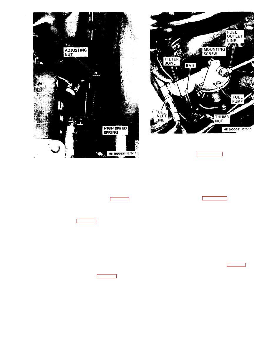 Figure 3-16. Fuel pump, installed view.
fuel pump as follows:
Figure 3-15. Governor spring adjustment
(1) Close fuel shut-off valve at the fuel tank.
(2) Disconnect fuel inlet and outlet lines from
the fuel pump.
(4) To decrease governed high speed, loosen the
(3) Remove two screws and lock washers securing
adjusting nut to decrease tension on the high speed
the pump assembly to the valve chamber cover. Re-
spring.
move the pump assembly and gasket from the engine.
(5) The engine may surge at high speed setting.
To correct surging, loosen the locknut (fig. 3-14) and
fuel pump assembly as follows:
turn the adjusting screw in until the engine runs
(1) Install fuel pump assembly and gasket on
smoothly.
valve chamber cover and secure with two screws and
(6) If the above does not correct surging, shorten
lock washers.
governor control rod (fig. 3-14) slightly by screwing
(2) Connect inlet and outlet fuel lines to the fuel
rod into clevis.
pump.
3-31. Fuel Pump Assembly
(3) Open shut-off valve at fuel tank.
(4) Start engine and check fuel pump operation.
a. General. The mechanically operated fuel pump
Check fuel lines for leaks.
is located on the left side of the engine below the air
e. Testing. If necessary, test the fuel pump pres-
cleaner.
sure as follows:
b. Service.
(1) Disconnect the fuel outlet line (fig. 3-16) from
(1) Inspect fuel pump assembly for cracks,
the fuel pump.
breaks, leaks, and secure mounting.
(2) Install a suitable adapter and fitting in the
(2) Loosen the thumb nut (fig. 3-16) and swing
outlet elbow. Connect a pressure gage to the fitting
bail to one side. Remove the filter bowl, screen, and
with a piece of rubber tubing less than 6 inches long.
gasket.
(3) Start the engine and run at idle speed with
(3) Clean bowl and screen with cleaning com-
fuel left in carburetor.
pound, solvent (Spec. P-S-661) and dry thoroughly.
(4) Pressure indicated on the gage is the static
Remove all sediment and lint from the screen.
pressure of the fuel pump. Pressure should be 3 psi
(4) Install gasket, screen, and bowl on fuel pump.
maximum.
Swing bail into place and tighten nut.
3-19
|
|
Privacy Statement - Press Release - Copyright Information. - Contact Us |
