 |
|||
|
|
|||
|
|
|||
| ||||||||||
|
|
 (2) Inspect large governor high speed spring
(2) Open the carburetor bowl drain and allow all
the fuel to drain into a suitable container.
field maintenance personnel if spring or governor
(3) Loosen clamp (fig. 3-13) and disconnect air
requires replacement.
cleaner hose from carburetor.
(4) Loosen screws and disconnect choke cable
(3) Attach a tachometer to the alternator pulley
and start the engine. Allow engine to warm up to
normal operating temperature.
(5) Remove cotter pin and clevis pin and discon-
(4) Open throttle wide open by depressing accel-
nect accelerator linkage from carburetor.
erator pedal all the way down. Speed should be ap-
(6) Remove cotter pin and disconnect governor
proximately 2,200 rpm. Engine should operate
rod from carburetor.
smoothly with no tendency to hunt (surge). Adjust
(7) Remove two screws (fig. 3-13), nuts, and lock
speed and surging (c below) if necessary.
washers securing carburetor to manifold flange.
Remove carburetor and gasket from manifold.
carburetor as follows:
(1) Install carburetor, with a new gasket, on
manifold flange and secure with two screws, nuts,
and lock washers.
(2) Connect governor rod to lever on carburetor
and secure with cotter pin.
(3) Connect accelerator linkage to throttle lever
on carburetor and secure with clevis pin and cotter
pin.
(4) Connect choke cable to bracket on carburetor
and tighten screws.
(5) Connect fuel line to carburetor inlet.
d. Adjustment. After installation, adjust carbure-
tor idle speed and idle mixture as follows:
(1) Before starting the engine, turn the idle stop
screw on rear side of carburetor against the stop to
hold throttle slightly open.
(2) Set idle mixture adjustment screw (fig. 3-13)
at approximately midposition.
(3) Start the engine (para 2-9) and allow engine
to warm up to normal operating temperature.
(4) Gradually turn idle mixture adjustment
screw in until engine begins to miss, Slowly turn
screw out until engine begins to run unevenly. Count
number of turns between two points.
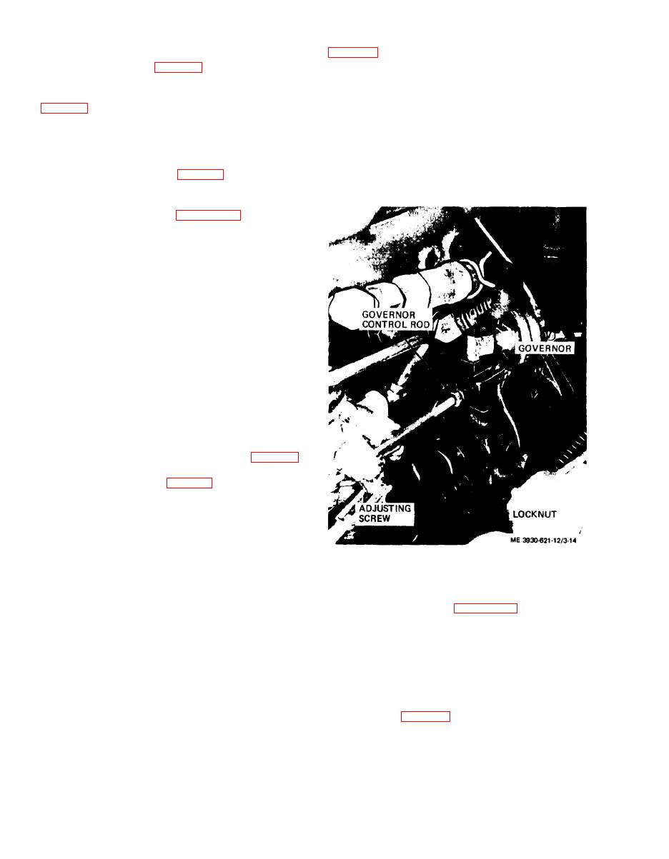
Figure 3-14. Governor, installed view.
(5) Rotate screw to bring it to approximately mid-
way between the two points reached in (4) above, or
until engine runs smoothly.
(6) Adjust idle stop screw to bring engine to an
idling speed of 500 to 550 rpm.
adjust governor as follows:
(7) After adjusting idle speed ((6) above), read-
(1) Adjust governor control rod so that lever on
just idle mixture adjustment screw to achieve smooth
carburetor is approximately 5 towards the closed
operation at normal idle speed.
position (to the left, facing the carburetor).
(2) Start the engine and allow it to reach normal
3-30. Governor
operating temperature.
a. General. The centrifugally operated governor is
(3) To increase governed high speed, tighten the
mounted in front of the carburetor and is driven by
adjusting nut (fig. 3-15) to increase tension on the
a gear. Adjustment is achieved by varying tension
high speed spring.
on the high speed spring.
b. Inspection
(1) Check governor and linkage for any damage.
3-18
|
|
Privacy Statement - Press Release - Copyright Information. - Contact Us |