 |
|||
|
|
|||
|
|
|||
| ||||||||||
|
|
 3-27. Engine Tests
b. Removal.
(1) Refer to paragraph 3-29 and remove the
a. General. The following tests aid in checking the
carburetor.
condition of the engine and aid in determining the
(2) Refer to paragraph 3-35 and disconnect the
repairs that may be required and also the extent of
exhaust pipe from the outlet flange.
those repairs.
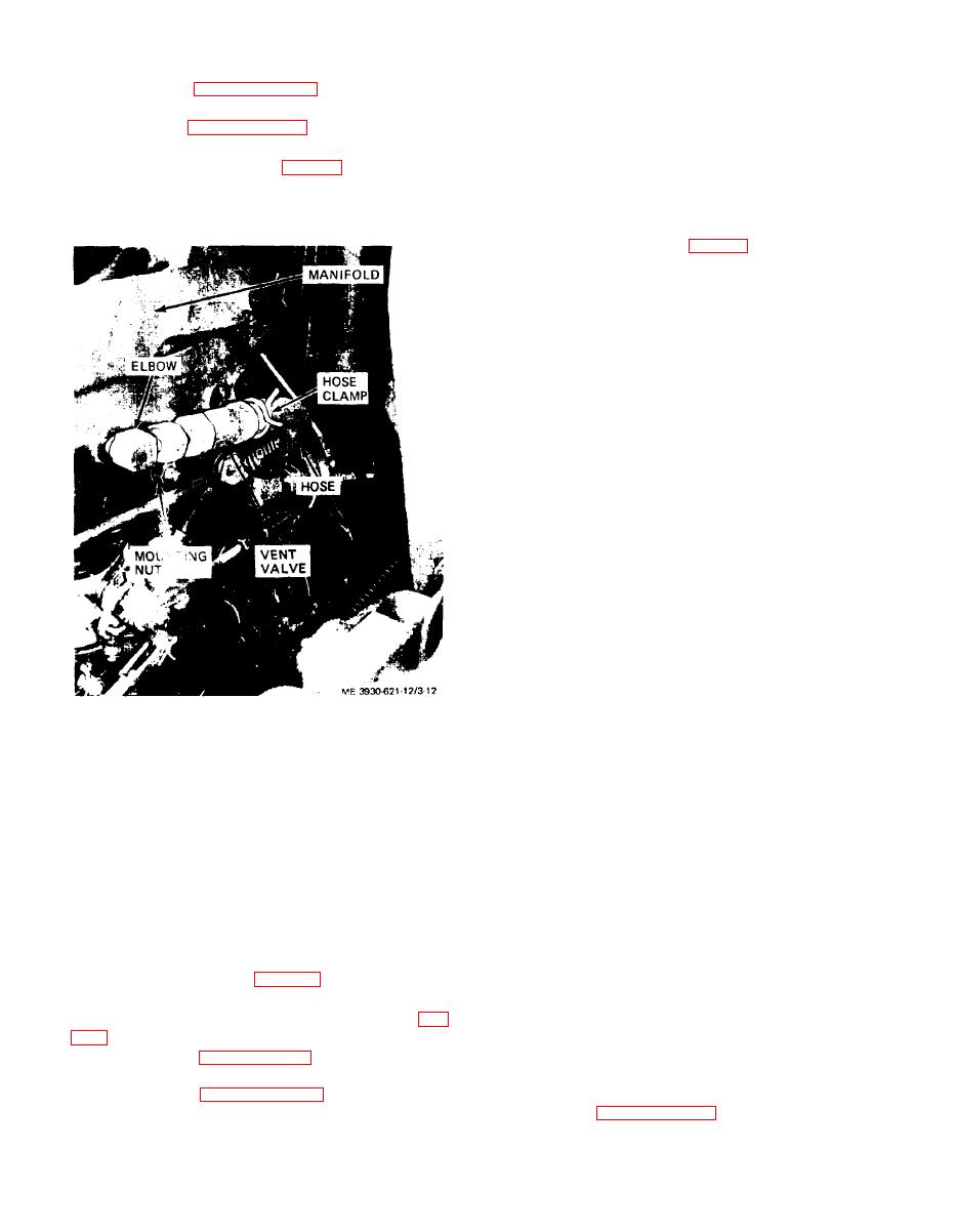
(3) Remove the hose clamps (fig. 3-12) and dis-
b. Compression Test. The compression test helps
connect the hose from the vent valve.
to determine the condition of rings, valves, and head
(4) Remove the vent valve and elbow from mani-
gasket. Check compression as described below.
fold.
(1) Start and operate engine at idle speed until
normal operating temperature (fig. 2-2, is reached.
(2) Shut off engine and leave ignition switch in
off position.
(3) Set carburetor throttle and choke controls in
the full open position.
(4) Remove the spark plugs. Install a compression
gage tightly in number one spark plug hole.
(5) Crank the engine with the starter to allow six
compression strokes on the gage. Note the readings.
(6) Repeat the test with the gage for each of the
remaining cylinders.
(7) Readings on gage should not vary more than
10 pounds. Starting speed normal compression
should be 120 to 125 psi.
(8) If any of the cylinders have low readings,
retest as follows:
(9) Add oil through the spark plug holes in an
amount sufficient to seal the piston rings.
(10) Crank the engine over five or six times to
allow oil to work down around rings and install gage
as above. Repeat test to obtain another compression
reading.
(11) If compression increases, defective or worn
pistons or rings are indicated.
(12) If compression does not increase, defective
Figure 3-12. Mainifold, installed view.
valves are indicated.
(13) If two adjacent cylinders show low readings,
(5) Remove six nuts and lock washers securing
a defective cylinder head gasket is indicated.
manifold to engine block and remove manifold and
(14) Install spark plugs and operate engine to
gaskets from engine.
check operation.
c. Cleaning and Inspection
c. Vucuum Test. Start engine and allow to reach
(1) Scrape all carbon and deposits from mani-
operating temperature. Shut off engine and discon-
folds.
nect vent valve hose and fitting from manifold (para
(2) Inspect manifolds for cracks.
3-26). Install a vacuum gage in intake manifold at
(3) Inspect vent valve hose for damage and
fitting opening. Vacuum test the engine as follows:
deterioration. Flush the valve with cleaning com-
(1) Start the engine and operate at idle speed.
pound, solvent (Spec. P-S-661) and dry thoroughly.
Observe the vacuum gage.
(4) Replace vent valve at least once a year.
(2) Normal vacuum of approximately 18.3 inch
d. Installation.
suction pressure should be indicated. Open throttle
(1) Install manifolds (fig. 3-12) with new gaskets
and observe gage. A drop of about 3.4 inches should
and secure with nuts and lock washers.
be noted. When throttle is closed, suction pressure
(2) Install elbows and connect vent valve (fig.
should increase to about 24 inches.
(3) A steady pressure of 15 to 16 inches indicates
(3) Refer to paragraph 3-29 and install the car-
pistons, piston rings, or lubricant are in poor condi-
buretor.
tion. Slight needle fluctuation indicates late ignition
(4) Refer to paragraph 3-35 and connect the
timing. Refer to paragraph 3-44 to time distributor
exhaust elbow to the manifold.
3-16
|
|
Privacy Statement - Press Release - Copyright Information. - Contact Us |