 |
|||
|
|
|||
|
Page Title:
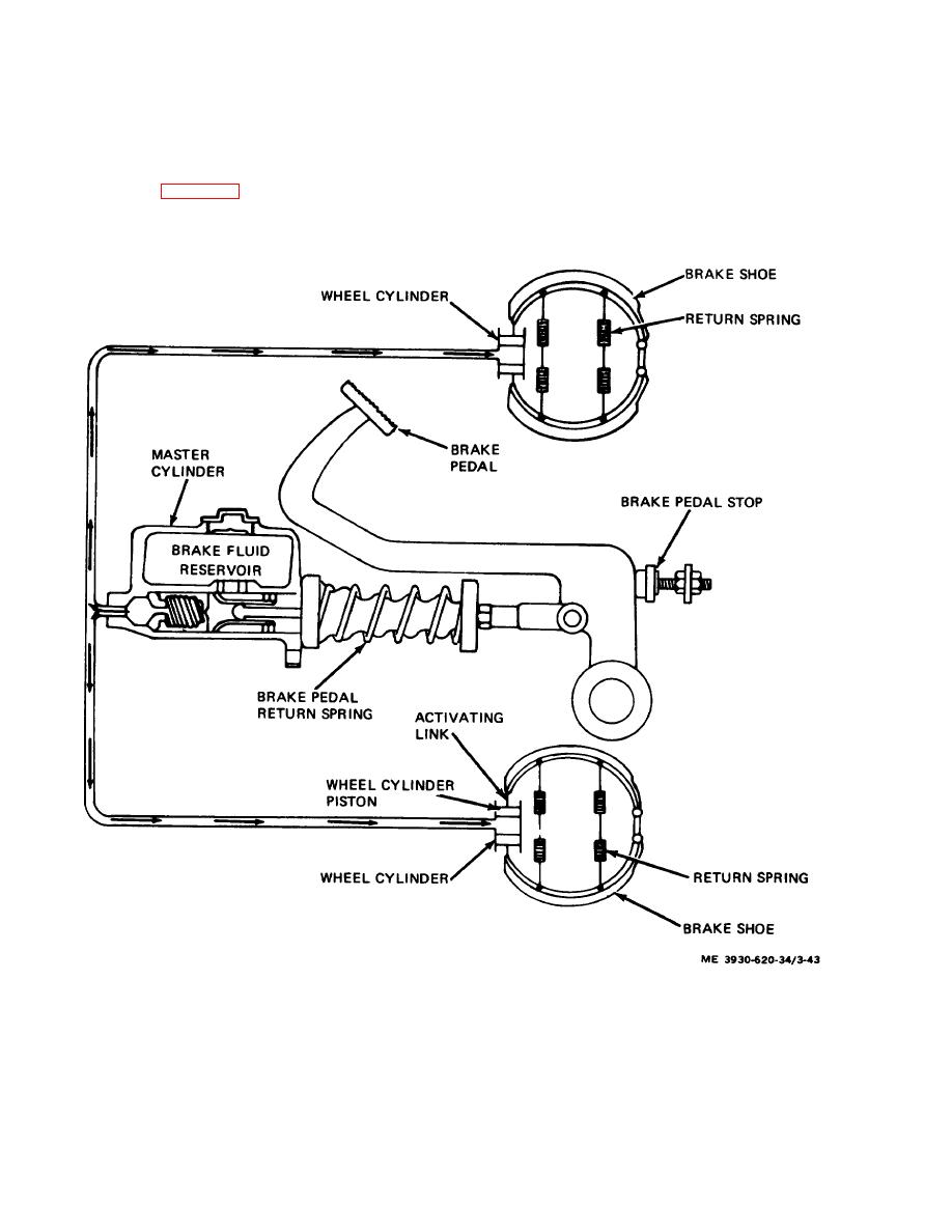
Figure 3-43. Hydraulic service brake system. |
|
||
| ||||||||||
|
|
 Section IV. SERVICE AND SEAT BRAKES
brake wheel AND SEAT BRAKES cylinders located
3-30. General
behind a dust shield in each of the drive wheels. The
a. A hydraulically operated, self-adjusting service
wheel cylinders are double end type. This type of cylinder
brake system is used in the lift truck to insure positive,
has activating links extending from each end of the
safe braking. (fig. 3-43.) The system consists of a
cylinder. These links transmit the movement from the
mechanically activated hydraulic master cylinder with
wheel cylinders to the brake shoes.
heavy duty brake lines transmitting hydraulic pressure to
Figure 3-43. Hydraulic service brake system.
b. The service brakes are self-adjusting through
expanding it. Link assemblies are attached to the brake
the use of a friction operated link assembly in each
shoes with roll pins. The pin mounting holes in the brake
wheel. The friction in the link assembly is great enough
shoes are 1/32 inch oversize to provide proper working
to prevent shoe return springs from collapsing the link,
clearance between shoe lining and brake drum.
but not enough to prevent pedal pressure from
3-63
|
|
Privacy Statement - Press Release - Copyright Information. - Contact Us |
