 |
|||
|
|
|||
|
|
|||
| ||||||||||
|
|
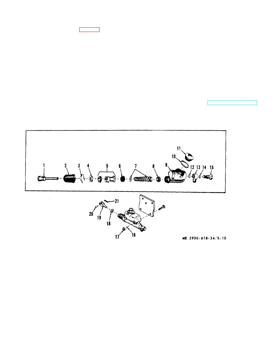 (1) Secure master cylinder in a vise, using
require honing to resurface the cylinder wall. Pressure
care not to crack or distort cylinder housing.
marks may be polished out with crocus cloth.
(2) Remove boot (2, fig. 5-15) and piston rod
(1).
CAUTION
(3) Hold piston in cylinder and remove lock
Do not use emery cloth or sandpaper.
wire (3) by gentle prying.
(3) Make sure intake and bypass ports are
CAUTION
open. Bypass ports may e probed with soft iron wire.
When lock wire is removed, the entire
(4) If it is necessary to resurface the cylinder
wall, follow the honing equipment manufacturers
piston assembly will spring out if not
recommendations. Do not hone cylinder oversize.
held in place.
(5) Before assembly, inspect parts for
(4) Carefully remove copper stop plate (4),
corrosion, scratched or pitted piston bearing surfaces,
piston (5), piston cup (6), spring (7), and valve (8).
rubber deterioration, and defective spring action.
(5) Working from the other end of cylinder,
Replace worn, damaged, corroded, or deteriorated parts
remove outlet fitting bolt (15), gasket (14), outlet fitting
as authorized.
(13), and gasket (12).
e. Assembly and Installation. Reverse procedures
(6) Remove filler cap (11) and gasket (10).
in b and c above. Refer to TM 10-3930-618-20 for
d. Cleaning and Inspection.
hydraulic brake bleeding.
(1) Clean all parts with denatured alcohol or
brake fluid, and keep clean in all following operations.
1 Piston rod
12 Gasket
2 Boot
13 Outlet fitting
3 Lock wire
14 Gasket
4 Stop plate
15 Fitting bolt
5 Piston assembly
16 Lockwasher
6 Piston cup
17 Capscrew
7 Spring and retainer
18 Jamnut
8 Check valve
19 Yoke
9 Cylinder and tank
20 Yoke pin
10 Gasket
21 Cotter pin
11 Filler plug
Figure 5-15. Master cylinder.
5-20
|
|
Privacy Statement - Press Release - Copyright Information. - Contact Us |
