 |
|||
|
|
|||
|
Page Title:
Figure 5-13. Wheel brake assembly (sheet 2 of 2). |
|
||
| ||||||||||
|
|
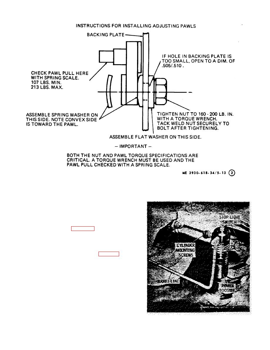 Figure 5-13. Wheel brake assembly (sheet 2 of 2).
5-14. Master Cylinder
a. Description. The brake master cylinder and fluid
reservoir are combined in one casting and are joined by
intake and bypass ports in the cylinder wall. Internal
parts are removable at the push rod end.
b. Removal. Refer to figure 5-14 and remove the
master cylinder assembly as follows:
(1) Remove the floor plate.
(2) Disconnect the electrical wires at the
stoplight switch.
(3) Remove the power booster (para 5-17).
(4) Remove the clevis pin holding the push
rod to the brake pedal.
(5) Remove the screws holding the master
cylinder assembly to the inside of the frame and remove
the cylinder.
Figure 5-14. Brake master cylinder installed view.
5-19
|
|
Privacy Statement - Press Release - Copyright Information. - Contact Us |
