 |
|||
|
|
|||
|
|
|||
| ||||||||||
|
|
 (d) Stroke each surface across the
abrasive several times and check the results. Any small
bright areas indicate a burr which must be removed.
When polishing the parts, hold them as flat as possible
against the abrasive. After 6-to-10 strokes across the
abrasive, check the part to see if it is polished. After
each part is polished, rinse clean in solvent', blow dry
with air, and place it where it can remain absolutely clean
until assembly.
(4) Replace all packing and oil seals.
Replace all other parts as authorized.
g. Assembly and Adjustment.
when assembling and adjusting.
(2) Control assembly.
(a) Install clean wooden block in vise to
provide platform for assembly operations.
(b) Place housing (48) on wood
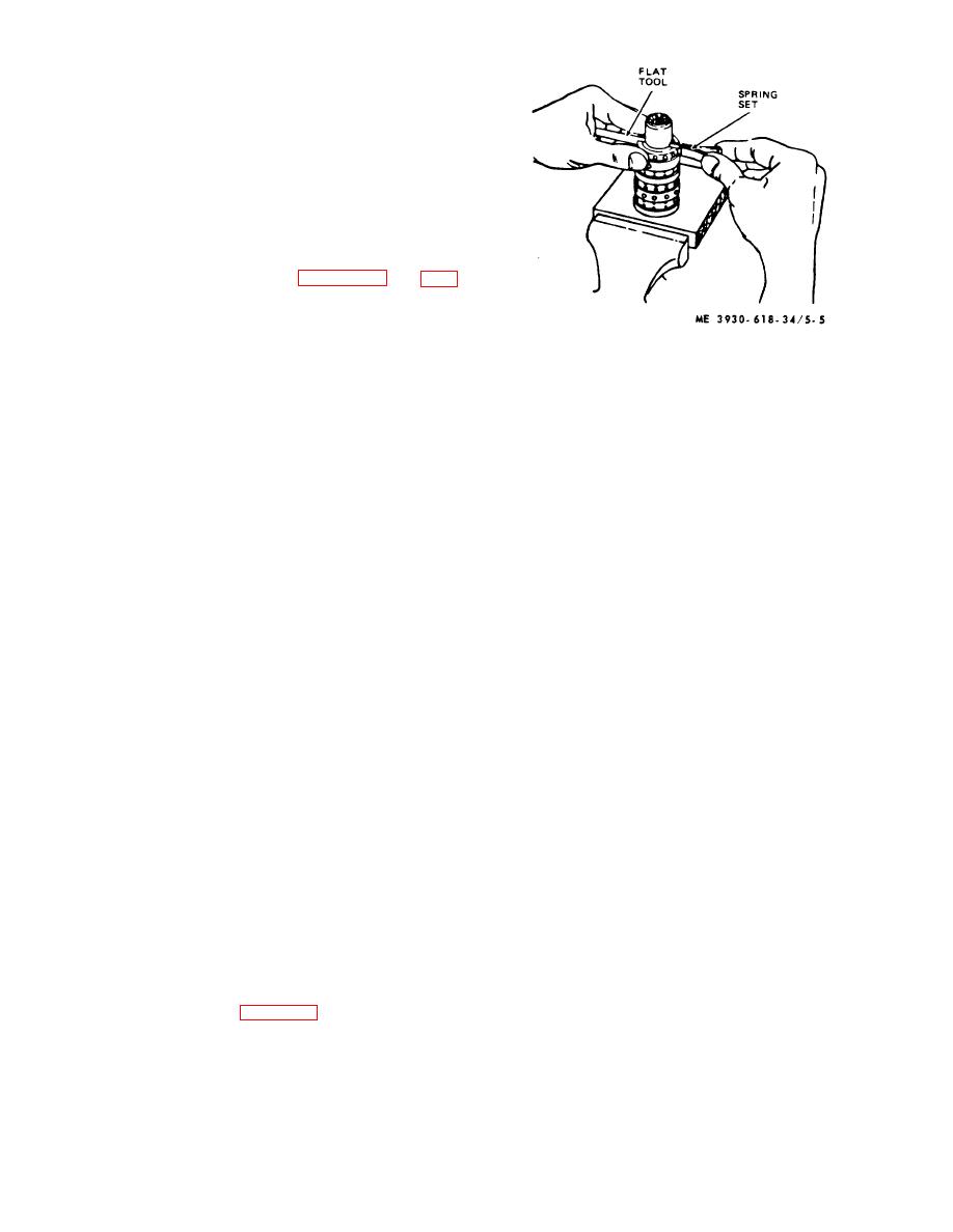
Figure 5-5. Installing centering spring set.
platform and drop check valve spring (47) into check
hole with large end down.
(I) Center spring set (42), alining each
(c) Drop check ball (46) into check hole
spring so the entire set is flush with upper surface of
making sure it rests on top of small end of spring (47).
control spool and sleeve.
(d) Place check valve seat (45) on
(m) Install the cross pin (41) through the
3/16inch hex wrench and screw into a check hole so
spool and sleeve and push into place until pin is flush or
machined counterbore of seat is towards ball (46).
slightly below the sleeve diameter at both ends.
(e) Lower wood platform in vise and
(n) Place the housing (48) on a solid
place housing (48) on platform control end up. Clamp
surface with the port face down. Install the spool
vise jaws lightly across housing port surface.
assembly with the splined end of the spool (50) entering
(f) Torque seat (45) to 150 inch-pounds
the 14-hole end of the housing first. Push parts gently
and test ball (46) action by pushing against it with small,
into place with a slight rotating motion.
clean pin.
CAUTION
NOTE
Use extreme care so control
Ball need not be snug against seat to
assembly (38) does not lose alinement
function properly.
when entering housing (48).
(g) Carefully install the spool (50) into
(o) Install control assembly (38) in
the sleeve (49). Be sure that spring slots of both spool
housing bore until flush with 14-hole end of housing.
and sleeve are at the same end. Rotate spool carefully
CAUTION
while sliding parts together. Test for free rotation.
Do not pull control assembly beyond
CAUTION
flush position or cross pin (41)will
Spool must rotate smoothly in sleeve
drop into housing discharge groove.
with finger tip force applied at splined
(p) Turn splined end of control
end.
assembly (38), checking for free rotation.
(h) Clamp wooden platform in jaws, set
(q) Install new packing (43) and check
control spool and sleeve on platform and aline spring
plug (44) in check plug hole. Use steady pressure on
slots of both.
plug and rock it slightly so packing feeds in smoothly
(i) Stand control spool and sleeve on
without cutting.
end and insert a flat tool through slots or both parts.
(r) Install new packing (40) and seal
(j) Position three pairs of centering
(24) on spool (50).
springs (42), or two sets of three each, on bench so
(s) Seat cap locator bushing (39), large
extended edge is down and center section is together.
outside diameter up, against spool (50) evenly.
(k) Install one end of positioned spring
h. Mounting Plate.
set (42) on flat tool. Compress extended end of spring
(1) Check mounting plate seal grooves for
set and push it into control spool and sleeve, withdrawing
cleanliness and smooth condition.
flat tool at same time. See figure 5-5.
(2) Install and smooth down new quad ring
shaft seal (24) and oil seal (16) into mounting plate (17)
seal grooves.
5-7
|
|
Privacy Statement - Press Release - Copyright Information. - Contact Us |
