 |
|||
|
|
|||
|
Page Title:
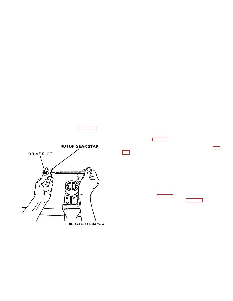
Figure 5-6. Drive-gear alinement. |
|
||
| ||||||||||
|
|
 (6) Push splined end of drive (23) through the
NOTE
gear until spline extends about one-half its length beyond
Oil seal (16) lip must face away from unit
gear star. Hold it in this position while installing it in the
unit. Note position or direction of cross pin (41) within
(3) Place the mounting plate subassembly
the unit.
over the spool shaft and slide it down smoothly in place
(7) Install gear-drive assembly into rotor ring
over the cap locator bushing (39) so that seals will not be
(21), drive (23) first, and slowly rotate it to engage cross
damaged.
slot in drive (23) with cross pin (41). Splined end of drive
(4) Aline the bolt holes in the cover (17) with
will drop down against rotor ring (21) when slot engages.
the tapped holes in the housing 1481. Be sure the
CAUTION
mounting plate' rests fairly flush against end of housing
assembly so that the cap locator bushing is not cocked.
Alinement of the cross slot in the
(5) Install mounting plate attaching bolts (18)
drive with the valleys between the
and torque each to 150 inch-pounds.
teeth of the gear star determines the
i. End Plate.
proper valve timing of the unit. There
(1) Reposition control housing (48) in vise,
are 12 teeth on the spline and 6 on
clamping the mounting plate with 14-hole surface up.
the star. Alinement will be right in 6
(2) Check that control spool and sleeve are
positions and wrong in 6 positions.
flush or slightly below 14-hole surface and that surface is
Should the parts slip out of position
clean.
during this part of the assembly,
(3) Place end plate (22) over control spool
make certain that proper alinement is
and sleeve, alining bolt holes in plate with tapped holes
obtained.
in housing 1481.
(8) Place end cap (20) over assembly and
(4) Place rotor ring (21) on assembly and
install screws (19) finger tight, to maintain alinement of
aline bolt holes.
parts.
(5) Place splined end of drive (23) in rotor
(9) Secure assembly in vise and torque
gear star so slot at control end of drive is alined with
screws to 150 inch-pounds.
outside diameter valleys of gear. See figure 5-6.
j. Installation.
(1) Install steering gear and secure steering
gear support (22, fig. 5-2) in place on truck bracket with
flat washers (23), lockwashers (24), and screws (25).
(2) Install clip on upper part of column (36, fig.
(3) Connect brush assembly connector (13).
(4) Note identification marks on hydraulic
hoses and attach hoses to proper ports in control
housing (48).
(5) Install floor and toe plates (TM 10-
3930618-20).
5-6. Shifting Mechanism
a. Removal.
(1) Remove floor plate (TM 10-3920-618-20)
and steering wheel (para 5-3).
(2) Remove roll pin (4, fig. 5-7) holding
indicator (3) in position and move indicator up shaft.
(3) Remove capscrews (1) holding cover (5)
in place and move out of way.
(4)
Remove capscrews from steering
column support (19) and the two mounting brackets (8
and 27).
Figure 5-6. Drive-gear alinement.
5-8
|
|
Privacy Statement - Press Release - Copyright Information. - Contact Us |
