 |
|||
|
|
|||
|
Page Title:
Section II. REPAIR OF HYDRAULIC LIFT CYLINDERS |
|
||
| ||||||||||
|
|
 compressed air. If filler screen cannot be cleaned,
4-4. Hydraulic Reservoir
replace with new filler screen.
a. Description.
The purpose of the hydraulic
d. Reassembly. Reverse the procedure as
reservoir is to hold sufficient oil for the entire hydraulic
outlined in c above.
system. It consists of a 7.2 gallon tank, combination filler
e. Installation. Refer to TM 10-3930-618-20 for
and plug and dipstick, and a washable breather cap. It is
hydraulic tank installation.
attached to the frame on the left side of the truck. The
suction line on one end of the tank is located near the
bottom to prevent air from being drawn into the pump,
causing pump noise and erratic operation of the system.
The return line is connected to the opposite end of the
tank, also near the bottom. This is to help prevent
foaming of the oil. A magnetic drain plug is provided on
the bottom of the tank to drain out all the oil when
necessary. A screen is located in the, auction line
between the reservoir and pump at the junction midway
of the line.
CAUTION
Always refer to LO 10-3930-618-12.
NEVER USE BRAKE FLUID. Make
sure containers and surrounding
parts are clean when filling tank, to
prevent dirt from contaminating the
oil.
b. Removal. Refer to TM 10-3930-618-20 for
hydraulic tank removal.
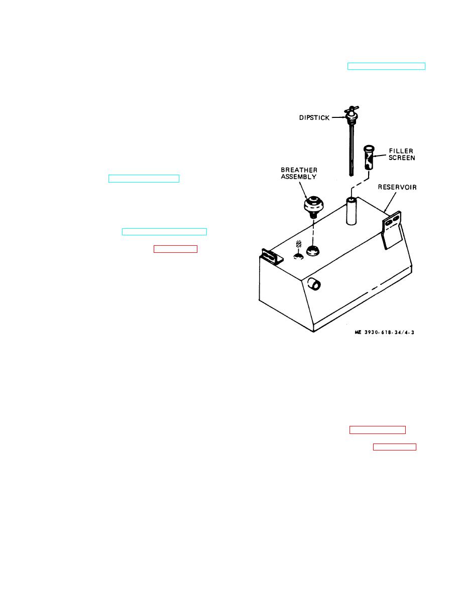
c. Disassembly. Refer to figure 4-3 and
disassemble the tank as follows:
(1) Remove all plugs, fittings, breather cap
and dipstick from the reservoir.
(2) Clean outside of reservoir with cleaning
solvent.
(3) Thoroughly flush reservoir with solvent to
remove dirt or other sediments.
(4) Inspect reservoir for bad dents, cracks,
and leaks. Replace reservoir if cracked or badly dented.
(5) Inspect for damaged or worn threads in
openings.
Repair damaged threads by chasing if
practical, otherwise replace the reservoir.
(6) Check filler screen for clogging or
Figure 4-3. Hydraulic reservoir.
damage.
Clean screen with cleaning solvent and dry with
Section II. REPAIR OF HYDRAULIC LIFT CYLINDERS
should not be called upon to hold any bending action due
4-5. Tilt Cylinders
to misalignment.
a. Description. The two double acting till cylinders
b. Removal.
Refer to paragraph 2-12 for tilt
provide the means for tilting the mast assembly 30
cylinder removal and installation.
forward and 100 back. They are located under cowls on
c. Disassembly.
Refer to figure 4-4 and
each fender. Action of the tilt cylinder is a straight line
disassemble the tilt cylinder as follows:
motion. Any misalignment between the cylinder and
(1) Secure tilt cylinder in bench vise. Be
piston will cause binding, rapid wear of packing and
careful not to deform cylinder.
packing gland, rapid wear of piston rod and packing, and
(2) Loosen capscrew in yoke (27) and
tend to break the weld on the cylinder case. The welded
unscrew yoke from plunger rod (16).
section is designed to hold hydraulic pressure and
4-6
|
|
Privacy Statement - Press Release - Copyright Information. - Contact Us |
