 |
|||
|
|
|||
|
|
|||
| ||||||||||
|
|
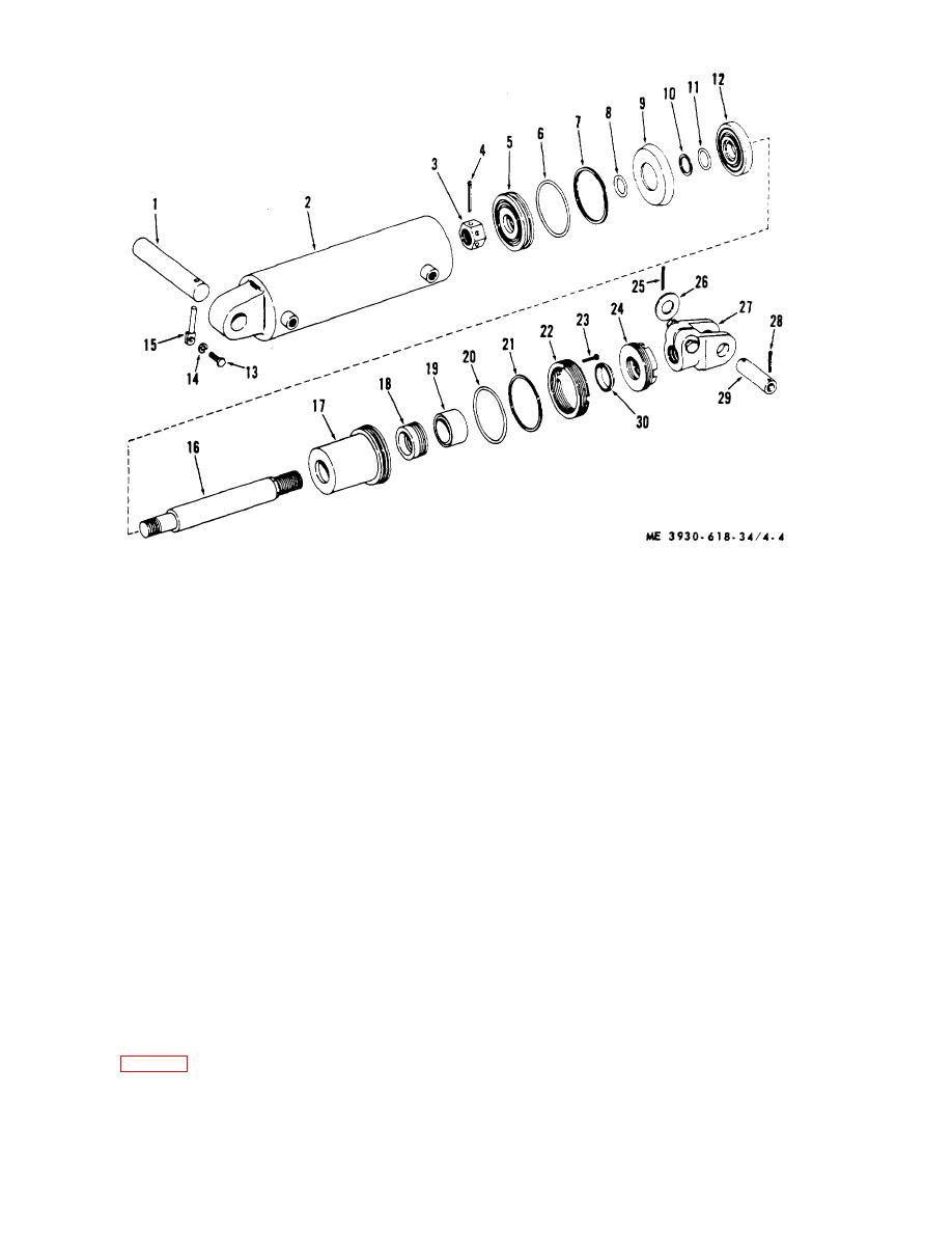 1 Pivot shaft
16 Plunger rod
2 Tube assembly
17 Stuffing box
3 Nut
18 Packing set
4 Cotter pin
19 Adapter
5 Guide ring
20 Ring
6 Packing
21 Packing
7 Backup ring
22 Retainer
8 Packing
23 Screw
9 Packing cup
24 Packing nut
10 Backup ring
25 Cotter pin
11 Packing
26 Flat washer
12 Follower
27 Yoke
13 Screw
28 Cotter pin
14 Lockwasher
29 yoke pin
15 Retainer
30 Wiper
Figure 4-4. Tilt cylinder.
(3) Remove bleeder screw from cylinder case,
4-6. Lift Cylinder
and insert airhose. With lift control valve held in down
a. Description. The lift cylinder is a piston type
(forward) position, blow oil out of cylinder back into
cylinder assembly. The plunger is bolted to the roller
reservoir.
support in the inner mast. The chain sprockets are also
(4) Disconnect hydraulic lines at lift cylinder.
mounted on this roller support.
(5) Wrap chain securely around outer case of
In operation, the plunger is moved upward by force of
cylinder assembly below lift chain anchor flanges.
hydraulic pressure at the plunger base, raising the
Attach hoist to chain and take up slack.
inner mast and carriage.
(6) Remove 2 screws attaching plunger to
b. Removal.
roller support on inner mast.
(1) Lower fork carriage, and remove carriage
(7) Lift cylinder assembly gently, to clear both
backrest (para 4-8).
upper and lower ends of cylinder from mast assembly,
(2) Detach chains from cylinder TM 10-
and remove.
3930618-20.
4-8
|
|
Privacy Statement - Press Release - Copyright Information. - Contact Us |
