 |
|||
|
|
|||
|
Page Title:
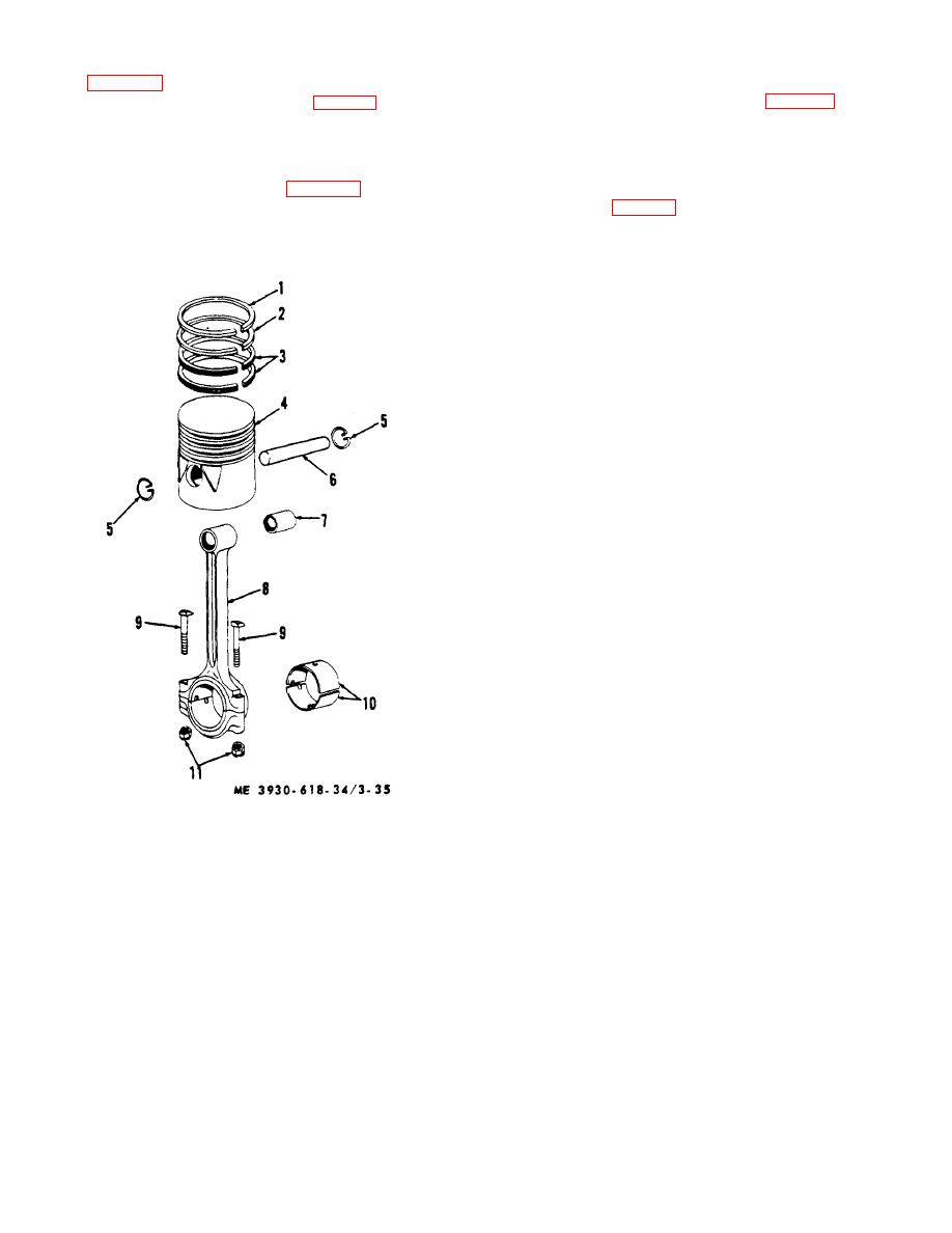
Figure 3-35. Piston and connecting rod. |
|
||
| ||||||||||
|
|
 (3) Drain oil from crankcase and remove oil
(6) Inspect, disassemble, and reassemble
pan (para 3-12).
pistons and connecting rods as required.
(4) If cylinder sleeves (2, fig. 3-32) are worn
(7) Inspect crankshaft 14, fig. 3-33) bearing
so there is a ridge at the upper end of ring travel, remove
journals at connecting rod throws for scoring, checking,
ridge with a ridge reamer before piston is removed. This
or signs of overheating. If any of these conditions exist,
prevents damage to rings during removal and
crankshaft will require reconditioning or replacing.
c. Disassembly.
installation.
(5) Remove nuts (11, fig. 3-35) and bearing
(1) Using suitable tool. remove piston pin
cap from each connecting rod (8) in turn and push piston
retainer ring (5, fig. 3-35 ) at each end of piston pin (6).
and connecting rod assembly out through top of cylinder
(2) To avoid breaking piston rings, the use of
block. Reassemble bearing caps on their respective
a ring remover and installer is recommended. Care must
connecting rods as they are removed.
be taken not to over-stress piston rings by spreading
ends more than is necessary to remove them from
piston. Before removing rings, inspect for wear and side
clearance in grooves.
However, removal will be
necessary in order to clean carbon from grooves.
(3) Using a driving tool, drive piston pin (6)
from piston. Use a wooden block or brass drift as a
driver. In some instances it may not be necessary to
drive piston pin from piston.
Specified clearance
between piston and pin at room temperature is 0.0001
inch to 0.0005 inch loose.
d. Piston and Piston Ring Inspection.
(1) As gummy deposits are not always
removed from piston walls and ring grooves with fuel,
these parts may be cleaned with Cleaning Solvent (Spec
P-S-661) and then blown off with dry compressed air.
After cleaning, piston skirt, piston rings, and ring grooves
should be thoroughly inspected.
CAUTION
Some types of solvents contain
chemicals injurious to aluminum
alloy. Do not use a cleaning agent
containing such chemicals.
(2) Piston skirt should be carefully inspected
for score marks or other indications of improper piston
clearance. Any scored pistons should be replaced.
(3) Inspect inside of piston for cracks, any of
which make it unfit for further use. Make certain that
drilled holes in piston walls are open and clean.
(4) Check piston for wear by inserting it into
cylinder sleeve and measuring clearance between piston
and sleeve. Maximum tolerance is from 0.0006 inch
tight to 0.002 inch loose, measured at bottom of piston
1 Top ring
skirt and at right angles to piston pin.
2 Second ring
3 Third and fourth ring
4 Piston
5 Pin retainer
6 Piston pin
7 Bushing
8 Connecting rod
9 Bolt
10 Rod bearing
11 Nut
Figure 3-35. Piston and connecting rod.
3-42
|
|
Privacy Statement - Press Release - Copyright Information. - Contact Us |
