 |
|||
|
|
|||
|
Page Title:
Figure 3-33. crankshaft gear and pulley. |
|
||
| ||||||||||
|
|
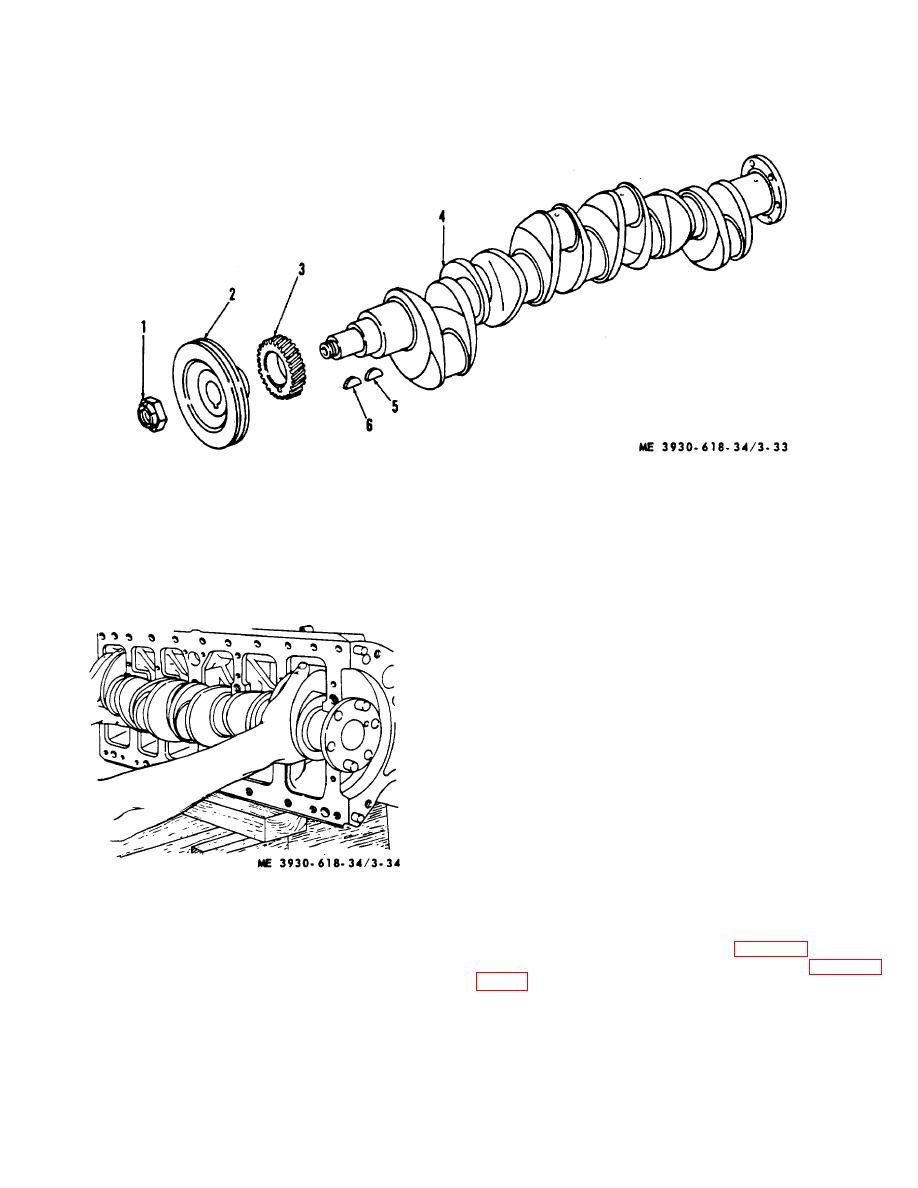 (2) Heat crankshaft timing drive gear (3) in
and camshaft gears and mesh gears. It may be
boiling oil for at least 15 minutes to expand gear ID.
necessary to tap gear with a wooden block and hammer
(3)
Pick up gear with tongs or pliers and
to seat it over key and against crankshaft shoulder.
slide onto crankshaft. Aline "C" marks on crankshaft
1 Locknut
2 Pulley
3 Gear
4 Crankshaft
5 Key, gear
6 Key, pulley
Figure 3-33. crankshaft gear and pulley.
grooves in pin boss of piston. Pins are full-floating, but
normal movement is between pin and bushing in the
connecting rod.
(2) Connecting rods. Each connecting rod,
made of drop-forged, heat-treated steel, is forged to an
"I" section with closed hub at upper end and integral cap
at lower end and is dynamically and electronically
balanced. Connecting rod bearings are replaceable
without machining.
Each half of bearing shell is
prevented from radial movement by a tang at parting line
on one side of bearing shell. Bearing shells are held in
place by a cap which is attached to the connecting rod
with two special capscrews and castellated nuts. Upper
end of connecting rod contains a bushing which is
pressure lubricated.
b. Removal. Connecting rods and pistons may be
Figure 3-34. Removing crankshaft.
replaced without removing engine from truck. (If engine
has already been removed from truck, disregard (1), (2),
3-22. Pistons and Connecting Rods
and (3) below).
a. Description.
(1) Remove cylinder head (para 3-20).
(1) Pistons.
The
precision-machined,
(2) Remove steering axle assembly (para 2-
balanced, cast aluminum alloy, cam ground, and tip-
plated pistons are fitted with two compression and two oil
control rings, all located above piston pin. Behind oil
control ring, holes drilled through piston allow excess oil
in groove to return to crankcase. Piston pins are full-
floating type held in piston by two retainer rings fitted into
3-41
|
|
Privacy Statement - Press Release - Copyright Information. - Contact Us |
