 |
|||
|
|
|||
|
Page Title:
Figure 3-5. Drive motor, disassembly and reassembly. |
|
||
| ||||||||||
|
|
 TM 10-3930-611-35
1.
Screw (8 reqd)
29.
Screw (4 reqd)
2.
Washer, lock (8 reqd)
30.
Washer, lock (4 reqd)
3.
Bearing bracket, drive end
31.
Connector (short)
4.
Ball bearing, drive end
32.
Connector (long)
5.
Screw
33.
Connector, cross (2 reqd)
6.
Cover (half)
34.
Insulator (10 reqd)
7.
Cover (half) with nut
35.
Ball bearing, front end
8.
Screw (4 reqd)
36.
Pin cover (4 reqd)
9.
Washer, lock (4 reqd)
37.
Yoke and bearing support
10.
Nut (10 reqd)
38.
Nut, shaft
11.
Washer, lock (10 reqd)
39.
Armature (complete)
12.
Nut, hex (ref item #10)
40.
Key, commutator
13.
Washer, lock (ref item #11)
41.
Key, armature
14.
Washer, flat (10 reqd)
42.
Shaft
15.
Screw (5 reqd)
43.
Nut (ref item #10)
16.
Washer, flat (ref item #14)
44.
Washer, lock (ref item #11)
17.
Screw (8 reqd)
45.
Nut, hex (ref item #10)
18.
Washer, flat (8 reqd)
46.
Washer, lock (ref item #11)
20.
Holder, brush (4 reqd)
47.
Washer, flat (ref item #14)
21.
Washer, insulating (4 reqd)
48.
Washer, flat (ref item #14)
22.
Screw (8 reqd)
49.
Screw (ref item #15)
23.
Washer, lock (8 reqd)
50.
Insulator (ref item #34)
24.
Brush (4 reqd)
51.
Screw (8 reqd)
25.
Screw (ref item #22)
52.
Pole, main (4 reqd)
26.
Washer, lock (ref item #23)
53.
Coils, field (1 set reqd)
27.
Bracket, angle (4 reqd)
54.
Frame
28.
Spring (8 reqd)
Figure 3-5. Drive motor, disassembly and reassembly.
(2) Refer to figure 3-6 and remove the
contactors, SCR panel, fuse holders, terminal strips and
time delay relay.
b. Cleaning and Inspection.
(1) Wipe all parts with a clean, dry cloth.
(2) Inspect for breaks, cracks, corrosion,
loose or missing mounting hardware, elongated
mounting holes, or other defects.
(3) Tighten or replace loose or missing
mounting hardware, replace a damaged contactor, SCR
panel, terminal strip, fuse holder or time delay relay as
necessary.
c. Installation.
(1) Refer to figure 3-8 and install the
contactor, SCR panel, fuse holders, terminal strips and
time delay relay.
(2) Install the control box, (para 3-4).
3-7. Wiring Harness
whether run individually or in a harness, are marked or
numbered. The vast majority of the electrical leads
have crimp-on connections at each end; some of the
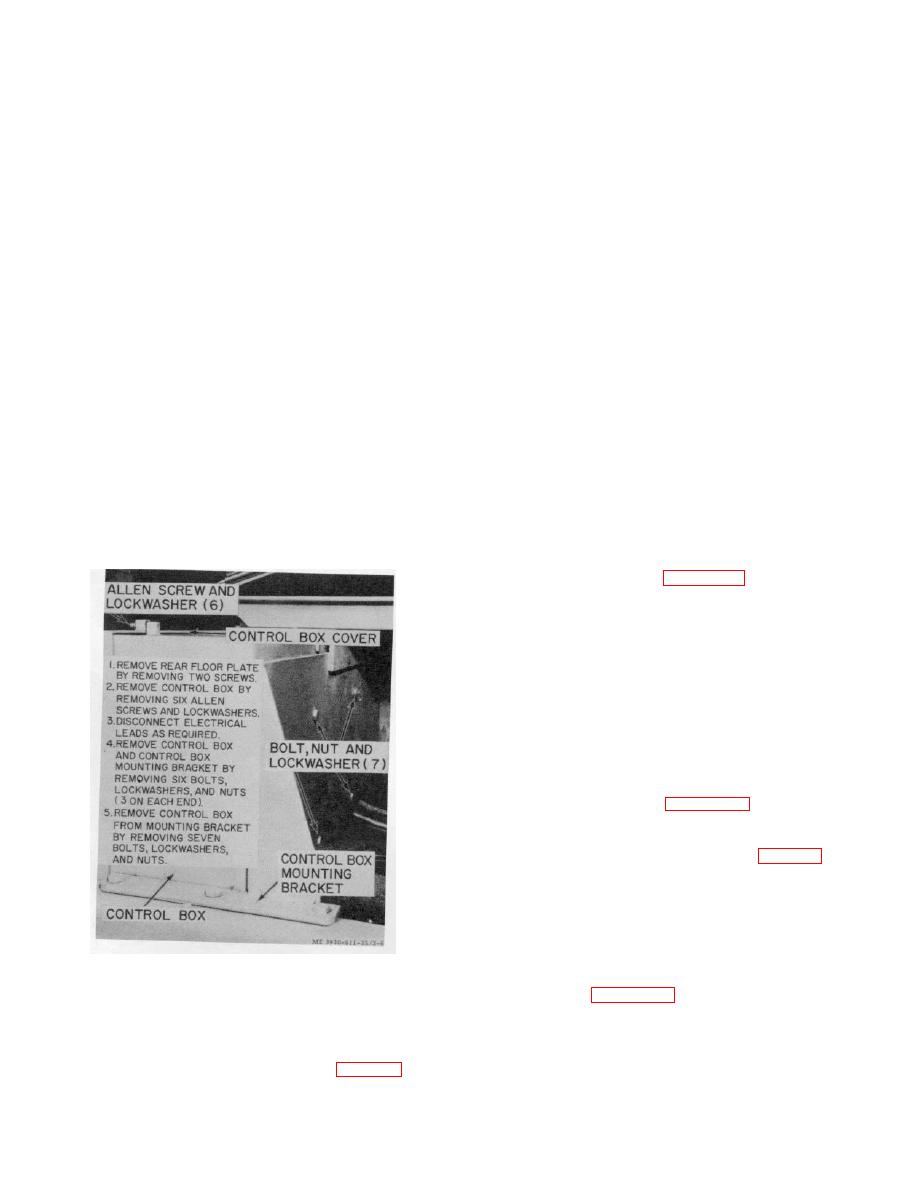
Figure 3-6. Control box, removal and installation.
components have quick disconnect type connectors on
the wire leads. Figure 3-6. Control box, removal and
installation.
3-6. Contractors, SCR Panel, Fuse Holders,
b. Inspection.
Inspect the insulation for
Terminal Strips and Time Delay Relay
cracks or frayed material. Pay particular attention to
a. Removal.
wires
(1) Remove the control box (para 3-4).
3-7
|
|
Privacy Statement - Press Release - Copyright Information. - Contact Us |
