 |
|||
|
|
|||
|
Page Title:
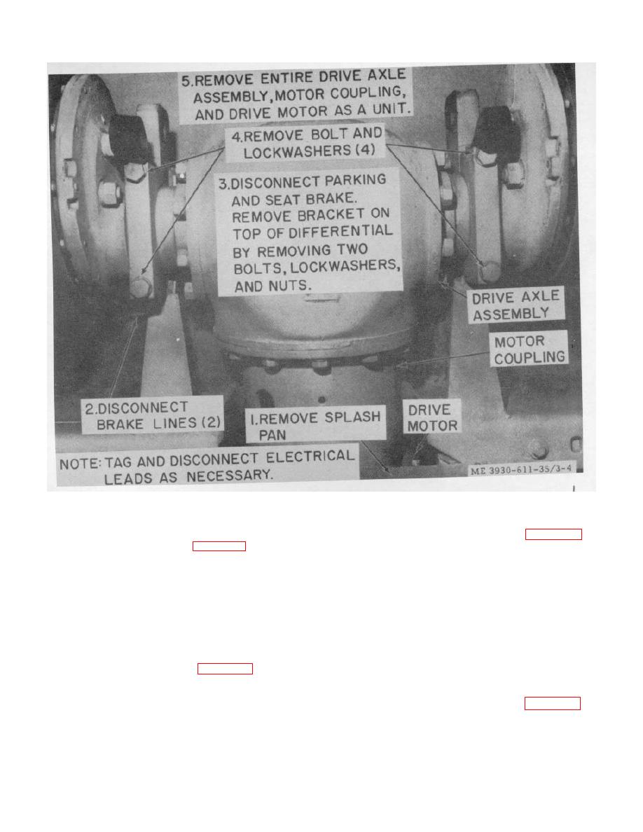
Figure 3-4. Drive motor, removal and installation. |
|
||
| ||||||||||
|
|
 TM 10-3930-611-35
Figure 3-4. Drive motor, removal and installation.
3-4. Control Box
disassemble the accelerator switch.
c. Cleaning, Inspection and Repair.
the control box.
b. Cleaning and Inspection.
(1) Wipe all electrical parts with a clean,
dry cloth. Clean all other parts with dry cleaning solvent
(1) Wipe the box with a clean, dry cloth.
(Federal Specification P-D-680) and dry thoroughly.
(2) Inspect for breaks, cracks, elongated
(2) Inspect all wires and terminals for
mounting holes, loose or missing mounting hardware, or
breaks and corrosion. Inspect all other parts for breaks,
other defects.
cracks, dents, loose or missing mounting hardware, or
(3) Tighten or replace loose or missing
other defects.
mounting hardware. Replace a damaged or defective
(3) Clean corrosion from wires and
control box as necessary.
electrical connections, and tighten or replace loose or
missing mounting hardware. Replace damaged parts as
the control box.
necessary.
d. Reassembly.
3-5. Accelerator Switch
Refer to figure 3-7 and
a. Removal. Refer to TM 10-3930-611-12 for
reassemble the accelerator switch.
e. Installation. Refer to TM 10-3930-611-12
removal of accelerator switch.
for installation instructions.
3-5
|
|
Privacy Statement - Press Release - Copyright Information. - Contact Us |
