 |
|||
|
|
|||
|
Page Title:
Test of Accelerating Control Potentiometer |
|
||
| ||||||||||
|
|
 2-5. Test of Accelerating Control Potentiometer
d.
With the accelerating control depressed to the
Operation of the potentiometer can be checked without
top SCR speed position (switch ASA2 just ready to
disassembling the control. Proceed as follows:
close), the resistance reading should be 200 ohms or
less.
a.
Disconnect battery and disconnect wire 29A
from either the thermal protector TP or the SCR
to the truck frame should be 1 megohm or higher.
b.
Connect ohmmeter from wire 29A and wire
f. If any of the resistance tests are unsatisfactory
13A negative and set meter to the RX100 range.
the accelerating control should be disassembled and
adjusted or repaired as indicated (para 104 and 105).
c.
With the accelerating control depressed to the
creep speed position (switch ASA1 just actuated), the
resistance reading should be between 3,500 and 6,600
2-6. Test of Rectifiers 3 REC and 4 REC
ohms.
These two diode rectifiers are identical. Before
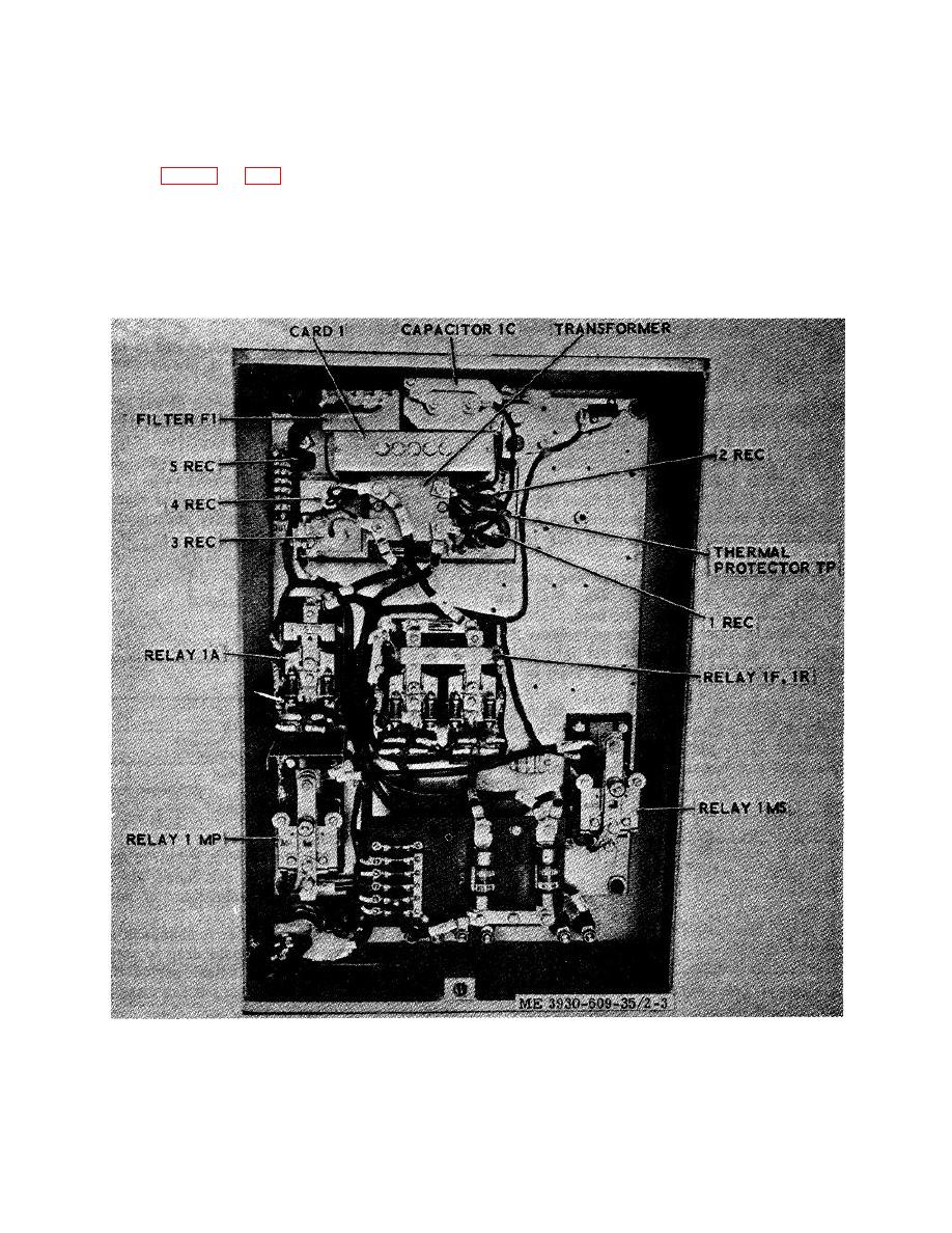
Figure 2-3. Control and SCR panel.
2-9
|
|
Privacy Statement - Press Release - Copyright Information. - Contact Us |
