 |
|||
|
|
|||
|
Page Title:
Test of SCR's (1 REC, 2 REC, 5 REC) |
|
||
| ||||||||||
|
|
 TM 10-3930-609-35
testing, disconnect battery, discharge capacitor IC to
d.
When replacing an SCR, apply thermal joint
prevent burning out ohmmeter, and disconnect pigtail of
compound or grease to mounting stud threads to
rectifier to be tested. With the ohmmeter set to the RX1
improve heat sinking (GE Versilube G-350-M or
scale, the resistance in the forward or conducting
equivalent is recommended). Tighten to a snug fit.
direction should be about 7 to 12 ohms. Measured on
the RX10,000 ohm range, the back resistance
2-8. Test of Card 1
(nonconducting direction) should be infinite. Allowing
The oscillator and timer sections of Card 1 may be
for meter and reading errors, replace any diode with
tested with simple test equipment after removal from the
resistance readings which are definitely outside the
panel. Remove card from panel by loosening two
specified values.
When replacing a diode, apply
screws at bottom of box and pulling box straight up to
thermal joint compound or grease to mounting stud
disengage from receptacle (fig. 2-3). Connections for
threads to improve heat sinking (GE Versilube G-350-M
the two tests may be made to card pins with insulated
or equivalent is recommended). Tighten to a snug fit.
clips.
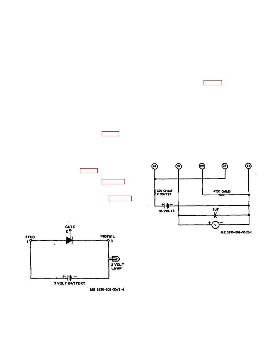
a. Oscillator Section.
2-7. Test of SCR's (1 REC, 2 REC, 5 REC)
(1) Connect the test circuit shown in figure 2-
These are silicon controlled rectifiers. Before checking,
5. Voltmeter should be on 10 or 15 volt range to start.
disconnect battery and discharge capacitor 1C to
(2) The initial voltage reading should be less
prevent burning out ohmmeter. Before checking 1 REC
than 10 volts. Adjust CREEP SPEED trimpot until
remove Card 1 to open gate and disconnect pigtail.
voltmeter reads 0.5 volts.
Before checking 2 REC, disconnect gate lead by
(3)
Remove capacitor across meter.
opening wire 8 to terminal 5 of filter Fl (fig. 2-3), and
Voltmeter should then read less than 0.1 volts.
disconnect the pigtail.
Before checking 5 REC,
(4) Failure to obtain the specified readings
disconnect gate lead by opening wire 12 to terminal 7 of
indicates that Card 1 is defective and should be
filter Fl, and disconnect the power lead to terminal on
replaced.
top of 5 REC. The test procedure for each SCR is the
same, as follows:
a. A 3 volt battery, a 3 volt lamp, and suitable
leads are required for the test (fig. 2-4). An equivalent
continuity test may be used.
the first test. The lamp should not light. If the lamp
lights the SCR is shorted and must be replaced.
circuit still connected, momentarily connect gate (point
2) to pigtail (point 3). The lamp should light and remain
lit when the gate con
Figure 2-5. Test circuit for oscillator section of card 1.
b.
Timer Section.
(1) Connect the test circuit shown in figure 2-
6 with voltmeter set on 50 volt range. The battery
switch should be a momentary of spring return type.
(2) Close switch and observe change in
voltage reading. The voltage should drop to zero in
approximately one second to indicate normal timer
action. Release switch .to open battery circuit as soon
as voltage drops to zero.
Figure 2-4. SCR test circuit.
(3) If the timer operates, but the time required
nection is removed. If this does not occur the gate is
inoperative and the SCR must be replaced.
2-10
|
|
Privacy Statement - Press Release - Copyright Information. - Contact Us |
