 |
|||
|
|
|||
|
|
|||
| ||||||||||
|
|
 UPRIGHTS
E. ASSEMBLY AND INSTALLATION
7. Slide inner upright into outer upright, adjusting
1. Install parts in the reverse order in which they
the rollers at the same time.
were removed.
NOTE:
2. If latches have been removed, make sure these,
The load rollers should be adjusted as tight
or new ones, are installed on the splines as they were
as possible and still allow the intermediate
originally. Retaining pine must not interfere with latch
upright to lower under its own weight. The
operation, and latches must be tight on the shafts.
amount of shims between the load roller and
Refer to "B", Figure 14.
stub shaft shoulder should be equal at this
point on both sides of the upright.
3. Check latching mechanism, to make sure that
Sufficient shims must be added to fill the
the right rear latch locks around the lug at the top of the
entire space between the load roller and its
outer upright when the upright assembly is collapsed.
retaining snap ring.
The mentioned latch is locked in position by the right
rear latch,
8. Add or delete shims under the strip bearing at
the top of the outer upright to hold the intermediate
4. Shim the cylinder guide shoes so the crosshead
upright in line with the outer upright when the two are
will be centered in the inner up right and So they will
extended.
slide freely on the guide rails, The total maximum
clearance should not exceed 1/16 inch.
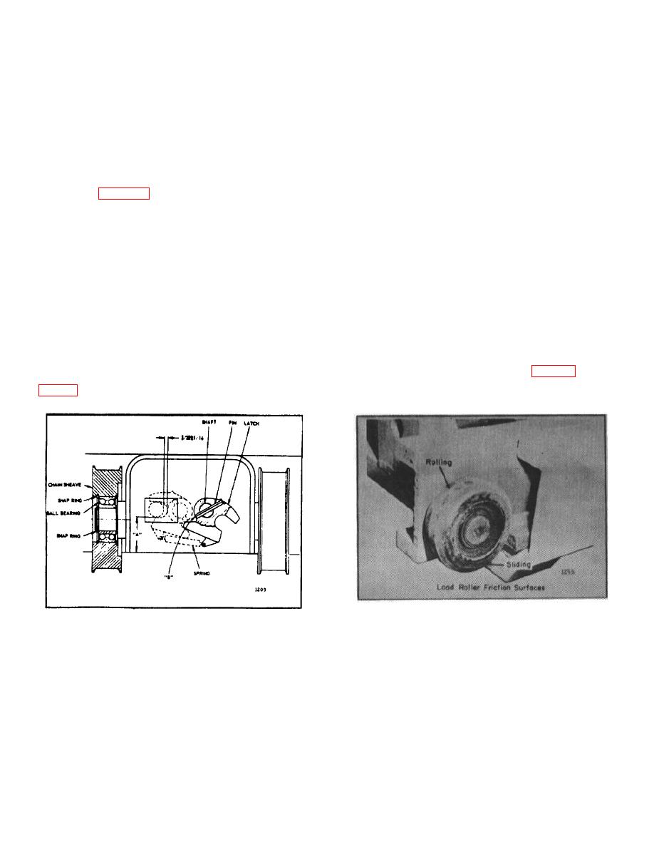
9. Apply a light coat of "Moly grease" to uprights
wherever the sides of the load rollers make contact. Do
5. There should be 3/32 inch, plus or minus 1/16
not grease the rolling surfaces as the roller may slide
inch vertical clearance, between the outer upright lug
instead of rotating during operation. (Figs. 15 and 16)
and its respective latch, when the upright is collapsed.
Apply grease to the intermediate upright-to-strip bearing
contacting surfaces.
Figure 14.
Figure 15.
6. Install all rollers, sheaves, bearings and shims in
10. Check the upright by extending the uprights and
their original places.
checking for binding, especially when the strip beargins
of the intermediate upright pass the strip bearings of the
outer upright. Binding at this point will cause excessive
wear and may prevent the lowering
B-176
|
|
Privacy Statement - Press Release - Copyright Information. - Contact Us |
