 |
|||
|
|
|||
|
|
|||
| ||||||||||
|
|
 ENGINE
the one removed. Dimensions of standard inserts and
counterbores are given in the Specification Listing.
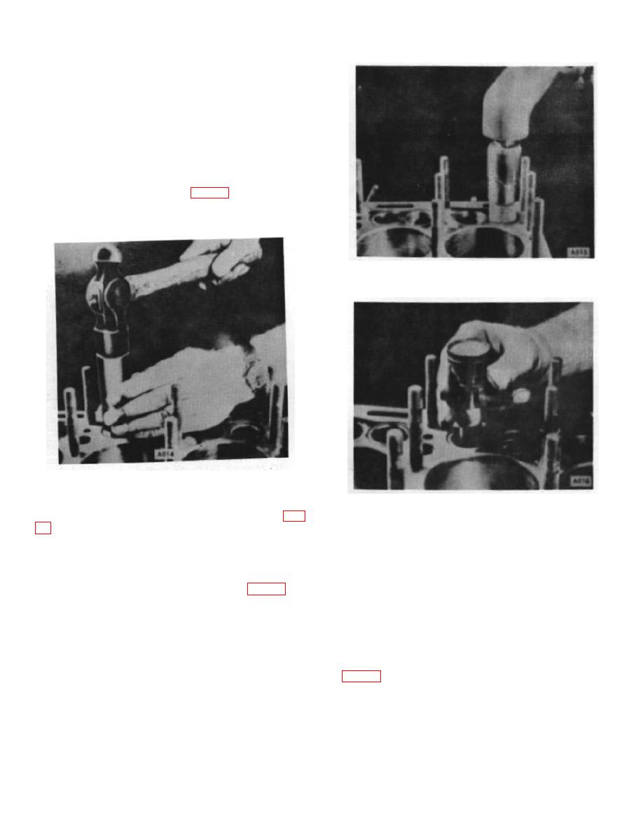
2. When oversize inserts are used, dimensions of
the insert and counterbore increase proportionately
(.010", .020", .030", depending on the oversize). New
insert installation should have a press fit. Chill insert
with dry ice for 20 minutes before assembling. Insert
may then be installed in the counterbore using a piloted
driver, tapping in place with very light hammer blows,
without shearing the side walls. (Fig. 13) This assures a
firm seating in the bottom of the counterbore, after
which it should be rolled in place.
Figure 14.
Figure 13.
Figure 15.
3. Grind the intake and exhaust valve seats (Fig.
D. VALVES
Before removing the arbor, check seat for runout. Total
indicator reading of the run-out must not be more than
1. Inspect valves and replace any that are
.002". Use a solid stem pilot with a long taper, as all
cracked, burned or which have stems that are bent or
valve seats must be ground concentric and square with
worn more than .002" over the maximum allowable
either new or worn valve stem guide holes. (Fig. 15)
limits. Reface or replace all valves.
2. All valves having less than 50% margin
thickness (outer edge of valve head) after refacing has
been completed, should be replaced. To check this
dimension, compare the refaced valve with a new valve.
B-5
|
|
Privacy Statement - Press Release - Copyright Information. - Contact Us |
