 |
|||
|
|
|||
|
|
|||
| ||||||||||
|
|
 ENGINE
D. PISTON PINS
3. Check the fit of the piston when it is
approximately 2" down in the cylinder bore in an
inverted position.
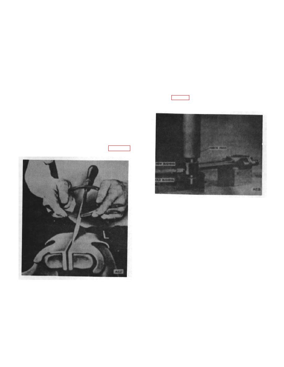
1. Check the bushing in the upper end of the
connecting rod for wear. If worn, and the original
C. PISTON RINGS
pistons are to be used with a service set of rings, an
oversize piston pin may be installed.
1. Check all piston rings in the cylinders for gap
whether using a re-ring set of piston rings in cylinder
2. The piston pin hole in the piston and the bushing
bores which have been ridge reamed or an oversize set
in the connecting rod maybe honed to increase their
for rebored cylinders.
diameter to obtain the desired fit. Replace the bushing
in the connecting rod, if new pistons are used. Using an
arbor press, press out the old bushing and press in the
2. To do this, insert a piston in the cylinder in an
new one. (Fig. 27) Then the bushing must be honed to
inverted position and then insert each ring, one at a
obtain the correct fit of the pin in the bushing.
time, about 2" down in the bore. Bring the bottom edge
of the piston up against the ring to square it up in the
cylinder bore.
3. Check the gap between the ends of the ring with
a feeler gauge in accordance with specifications. If any
of the rings do not have enough gap, they may be filed
by clamping the file in a vise and holding the ends
against opposite sides of the file as shown in Figure 26.
Figure 27.
3. If there is an excess of stock in the piston pin
bushing, it may be reamed first, then honed. In any
event, the final operation should be done with a hone to
obtain the desired fit with better than 75% bearing area
on the pin.
NOTE:
For bearing inspection refer to Main
Bearing Section.
E. ASSEMBLY AND ALIGNING
1. Assemble the pistons on the connecting rod by
Figure 26.
first heating them in some form of
B-9
|
|
Privacy Statement - Press Release - Copyright Information. - Contact Us |
