 |
|||
|
|
|||
|
Page Title:
Figure 3-105. Axle assembly, removal and installation. |
|
||
| ||||||||||
|
|
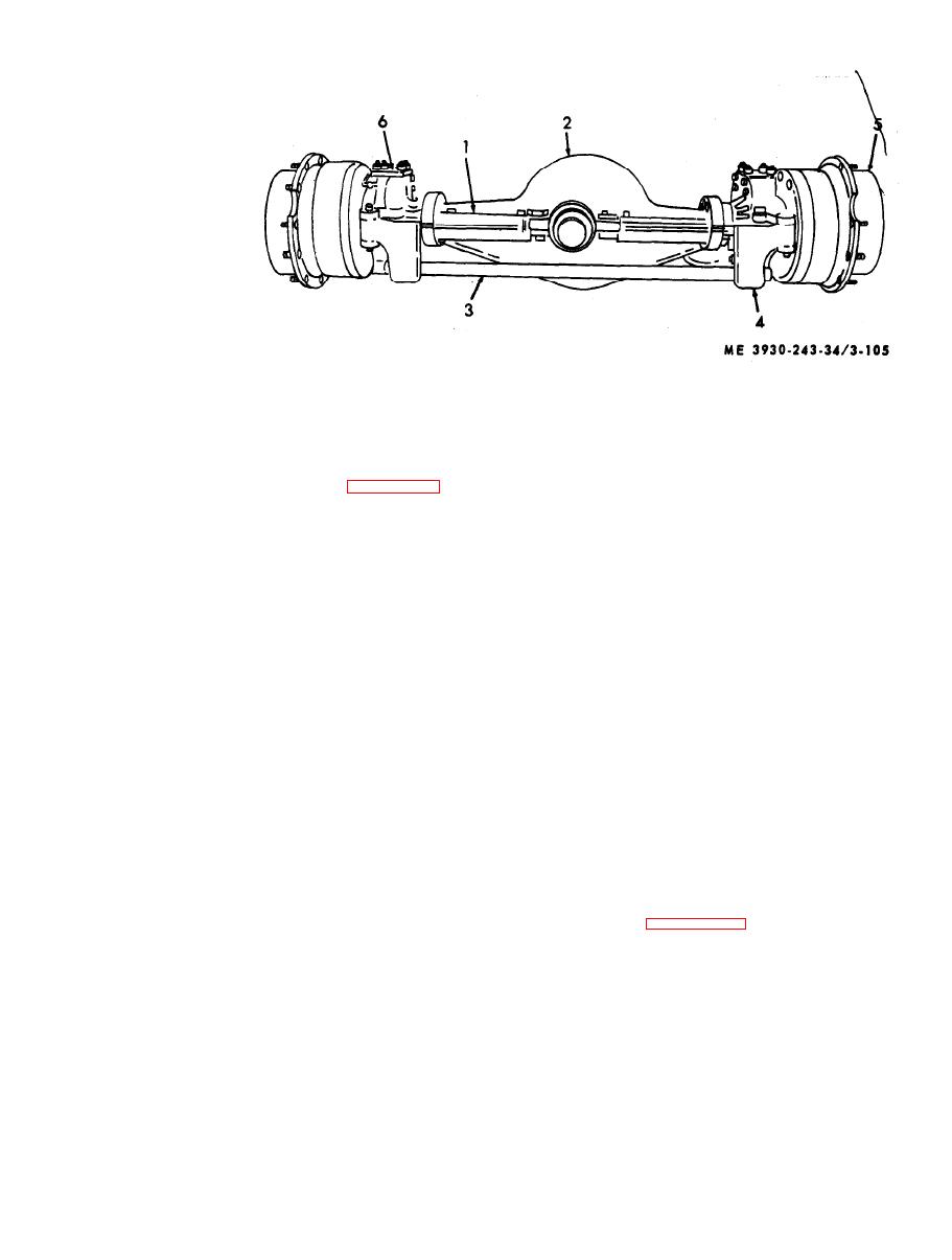 1 Steering cylinder
4 Tie rod yoke
2 Axle housing
5 Planetary gear housing
3 Tie rod
6 Ballhousing
( 1 0 ) Disassemble the differential assembly (93
thru 115).
disassemble the front axle assembly as described
below.
NOTE
Punch mark case (97), gear (114) and case (115) to
NOTE
identify for proper reassembly.
Before disassembly of axle, remove plug (28) and
drain oil from the hub assembly (27) and remove
c. Inspection and Repair.
plug and drain oil from the axle housing (124).
for excessive wear, looseness, ridges, pitting and
(1) Remove the planetary gears and hub (1
scoring.
thru 20). Do not disassemble the spider assembly
( 2 ) Inspect axle shafts for torsional fractures,
unless necessary.
s t r e s s , excessive wear or other impending failures.
( 2 ) Remove the planetary drive gear and hub
(3) Inspect housing for cracks or damage.
assembly (21 thru 35).
( 4 ) Replace parts if worn, pitted or damaged.
( 3 ) Remove the brake hose at fitting connector
Replace all gaskets and seals with new parts.
( 3 9 ) and remove the brake assembly (36 thru 40).
(5) Remove nicks, burrs, and mars from
( 4 ) Remove the spindle assembly (41 thru 45)
machined or ground surfaces with crocus cloth.
and remove the axle (46) from housing (58) and
I n s u r e that threads are clean and free and not worn
(61).
beyond limitations.
( 5 ) Remove and disassemble the front housing
d. Reassembly.
(47 thru 59) and remove the socket (60) and
remove the rear housing (61 thru 63).
NOTE
( 6 ) Remove opposite axle and steering support
Refer to current lubrication order for bearings, shaft.
gear, differential oil and other intricate moving parts
in the same manner as described above.
which require proper lubrication.
NOTE
(1) Refer to figure 3-106 and reassemble the
Both axles must be removed in order to remove the
a x l e assembly. Reassemble in the reverse order of
differential carrier.
disassembly.
(7) Remove the carrier assembly (921. Break
(2) Install mounting hardware 116 thru 123
carrier loose from the axle housing (124) with a
on axle housing (124).
rawhide mallet.
(3) Reassemble the differential assembly (93
NOTE
t h r u (115) as follows:
Do not disassemble the carrier assembly unless
(a) Attach ring gear (114) to case (115)
absolutely necessary.
with screws (111 and 113) and nut (114).
(8) Center punch cm differential carrier leg
(b) P r e s s b e a r i n g ( 9 4 ) o n d i f f e r e n t i a l c a s e
(92) and bearing cap (91) to identify for proper
(97) and (115).
reassembly and remove the differential assembly.
(c) A s s e m b l e n o s p i n a s s e m b l y ( 9 8 t h r u
110) and place this assembly on flanged differential
(9) Remove differential yoke, bearings and
pinion gear (64 thru 84).
case (115).
|
|
Privacy Statement - Press Release - Copyright Information. - Contact Us |
