 |
|||
|
|
|||
|
Page Title:
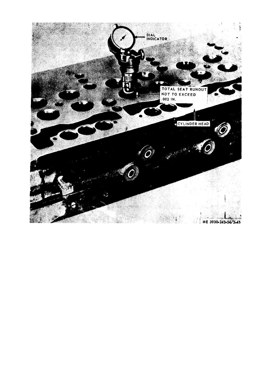
Figure 3-45. Checking relative concentricity of exhaust valve seat insert with relation to valve guide. |
|
||
| ||||||||||
|
|
 seat insert with relation to valve guide.
m. Install Exhaust Valves and Springs. With the
(2) Hold the valves in place with a strip of
masking tape and turn the cylinder head right side
cylinder head cleaned, the valve guides checked or
up on the work bench. Place a board under the
replaced, the valves and valve seat inserts ground,
head to support the valves and to provide clearance
install the exhaust valves and springs as follows:
between the cam followers and the bench.
(1) Apply a light coat of engine oil on the valve
(3) Install the valve guide oil seals, if used, on
stems and install the valves in the cylinder head. If
the valve guides.
reconditioned valves are used, install them in the
(4) Install the valve springs and valve spring
s a m e relative location from which they were
caps.
removed.
(5) Thread the valve spring compressor into
NOTE
one of the rocker shaft bolt holes in the cylinder
The distance from the top of the cylinder head to the
head.
bottom of the valve spring seat counterbore is 1-
11/64 inch. The valve spring lock groove in exhaust
(6) Apply pressure to the free end of the tool to
valves is 0.310 inch from the end of the valve.
compress the valve spring and install the two piece
|
|
Privacy Statement - Press Release - Copyright Information. - Contact Us |
