 |
|||
|
|
|||
|
Page Title:
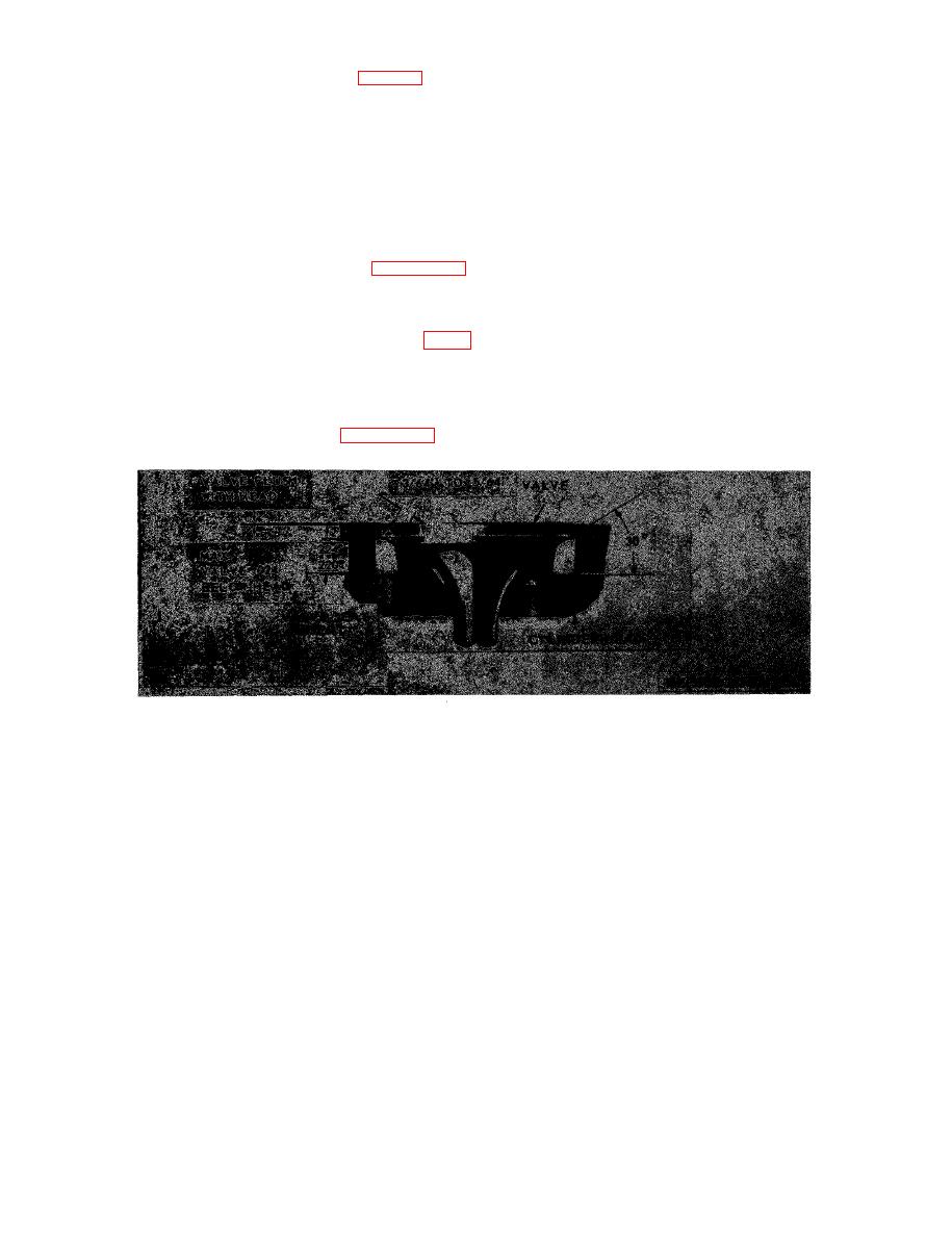
Figure 3-44. Relationship between exhaust valve, insert and cylinder head. |
|
||
| ||||||||||
|
|
 specified 3/64 inch to 5/64 inch (fig. 3-44). The
rotate it to determine the concentricity of each valve
30 face of the insert may be adjusted, relative to
seat insert relative to the valve guide. Total runout
t h e center of the valve face, with the 15 to
must not exceed 0.002 inch. If a runout of more
0 grinding wheels.
than 0.002 inch is indicated, check for a bent valve
guide before regrinding the insert.
CAUTION
(5) When a valve seat insert runout within the
For best results, do not permit the
desired limits is obtained, determine the position of
g r i n d i n g wheel to contact the cylinder
the contact area between the valve and the valve
h e a d when grinding the inserts.
seat insert as follows:
The position of the exhaust valve (when the valve is
(a) Apply a light coat of valve grinding
i n the closed position), to maintain the proper
c o m p o u n d paste to the valve seat insert.
piston-to-wall clearance is shown in figure 3-44.
(b) Lower the stem of the valve in the valve
Grinding will reduce the thickness of the valve seat
guide and bounce, but do not rotate, the valve on
i n s e r t and cause the valve to recede into the
the insert. This procedure will indicate the area of
cylinder head. If, after several grinding operations,
contact on the valve face. The most desireable area
the valve recedes beyond the limits shown in figure
of contact is at the center of the valve face.
3-44, replace the valve seat insert.
( 6 ) After the valve seat inserts have been
( 4 ) After the grinding has been completed,
ground and checked, thoroughly clean the cylinder
clean the valve seat insert thoroughly with fuel oil
head before installing the valves.
and dry it with compressed air. Set the dial in-
dicator in position as shown in figure 3-45 and
|
|
Privacy Statement - Press Release - Copyright Information. - Contact Us |
