 |
|||
|
|
|||
|
Page Title:
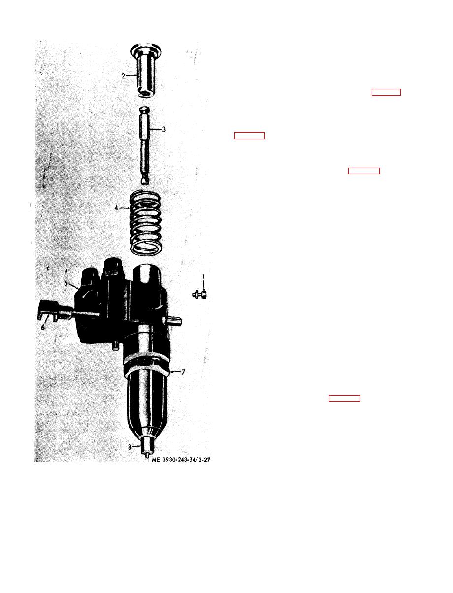
Figure 3-27. Injector follower, spring and plunger, removal and installation |
|
||
| ||||||||||
|
|
 e. Cleaning and Inspection. Since most injector
difficulties are the result of dirt particles, it is
essential that a clean area be provided on which to
place injector parts after cleaning and inspection.
(1) Clean out all passages, drilled holes and
slots in the injector.
(2) Clean the spray tip with reamer (fig. 3-28).
Turn reamer in a clockwise direction to remove
carbon deposits.
(3) Clean the spray tip orifices with pin vise
tool using the proper size spray tip cleaning wire
holes.
(4) Clean and brush all passages in injector
body. Carefully insert reamer into the injector nut
and ream injector spray tip seat (fig. 3-30). Turn
reamer in a clockwise direction to remove carbon
deposits.
(5) Inspect the teeth on the control rack and
control rack gear for wear and damage. Inspect
both ends of spill deflector for sharp edges or burrs.
Remove burrs with a medium stone.
(6) Inspect follower spring for defects and
proper tension. The spring has a free length of
approximately 1.504 inches. Replace spring when
load of less than 70 pounds will compress it to
1.028 inch.
(7) Check seal ring area in the injector body
and surface which contacts the injector bushing for
damage. If necessary lap this area.
(8) Inspect the injector plunger for scoring,
erosion chipping or wear. Check for sharp edges on
portion of plunger which rides in the gear. Remove
any sharp edges with a 500 grit stone and clean.
Slip the plunger into the bushing and check for free
movement. R e p l a c e w o r n , c h i p p e d , o r s c o r e d
plungers and bushings as an assembly since they
are mated parts.
( 9 ) Excessive spray tip seating surface of
injector nut for nicks, burrs, or brinelling.
(10) Inspect the sealing surfaces of injector
parts as indicated by arrows (fig. 3-31). Inspect all
surfaces with a magnifying glass, for even the
slightest imperfection will prevent injector from
operating properly. Check for burrs, nicks, erosion,
cracks, chipping, and excessive wear. Inspect spray
tips for enlarged orifices.
5 Body
1 Stop pin
6 Control rack
2 Follower
7 Nut
3 Plunger
8 Spray tip
4 Follower spring
and installation.
|
|
Privacy Statement - Press Release - Copyright Information. - Contact Us |
