 |
|||
|
|
|||
|
Page Title:
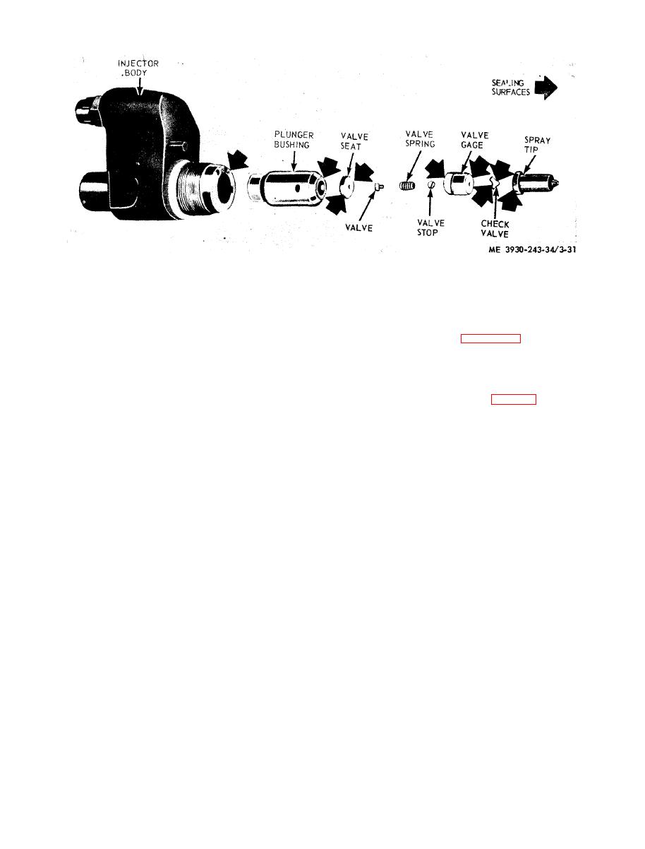
Figure 3-31. Fuel injector sealing surfaces which may require lapping. |
|
||
| ||||||||||
|
|
 f. Lap Injector Parts.
figure eight motion. Lapping the dry part in this
(1) Clean the lapping blocks with compressed
manner gives it the "mirror" finish required for
perfect sealing.
air.
(2) Spread a good quality, 600 grit dry lapping
3-27 and reassemble the fuel injector. Reassembly
powder on one of the lapping blocks.
is the reverse procedure of disassembly.
(3) Place the part to be lapped flat on block,
h. Spray Tip Concentricity Check.
using a figure eight motion, move it back and forth
across block. Do not press on part, but use just
(1) Place injector in the concentricity gage and
set dial gage indicator to zero (fig. 3-32).
enough pressure to keep the part flat on the block.
When part is flat, wash in solvent (P-D-680) and
(2) Rotate injector 360 and note total run-
out as indicated on dial.
dry thoroughly with compressed air.
(3) If total run-out exceeds 0.008 inch, remove
(4) Place the dry part on a second block;
injector from gage. Loosen injector nut, center the
a p p l y lapping powder and repeat action.
spray tip, and tighten nut to 55 to 65 foot pounds
(5) Place the dry part on a third block, Do not
torque. Recheck the spray tip for concentricity.
use lapping powder on this block. Keep the part flat
and move across block several times, using the
|
|
Privacy Statement - Press Release - Copyright Information. - Contact Us |
