 |
|||
|
|
|||
|
|
|||
| ||||||||||
|
|
 TM10-3930-242-12
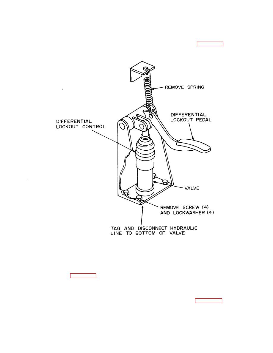
bleeder valve is provided at the lockout mechanism
and deterioration. Check for loose connections.
mounted on the differential to remove air from
Tighten loose connections and replace all defective
parts.
system. Replace the rubber boot on the valve
assembly.
(2) To service, lift the rubber boot on the valve
assembly and fill to within inch from top with OE
10 oil or brake fluid HBA (MIL-H-13910). Depress
the differential lockout control.
pedal several times and recheck fluid level. A
TA072427
(b) Remove two nuts, lockwashers, and
screws attaching throttle pedal to mounting plate
a. Removal. Refer to figure 4-33 and remove the
and cockpit floor. Remove pedal.
foot controls as follows:
b. Inspection. Inspect the foot controls for broken
(1) Brake Pedal and Inching PedaL Remove
or missing hardware, cracks, and damaged parts.
cotter pin and pin attaching each pedal to its
Replace all defective parts.
linkage. Remove pedal.
(2) Throttle Pedal.
foot controls as follows:
(a) Remove cotter pin and pin attaching pedal
(1) Broke Pedal and Inching Pedal. Bet pedals
to throttle linkage.
|
|
Privacy Statement - Press Release - Copyright Information. - Contact Us |
