 |
|||
|
|
|||
|
Page Title:
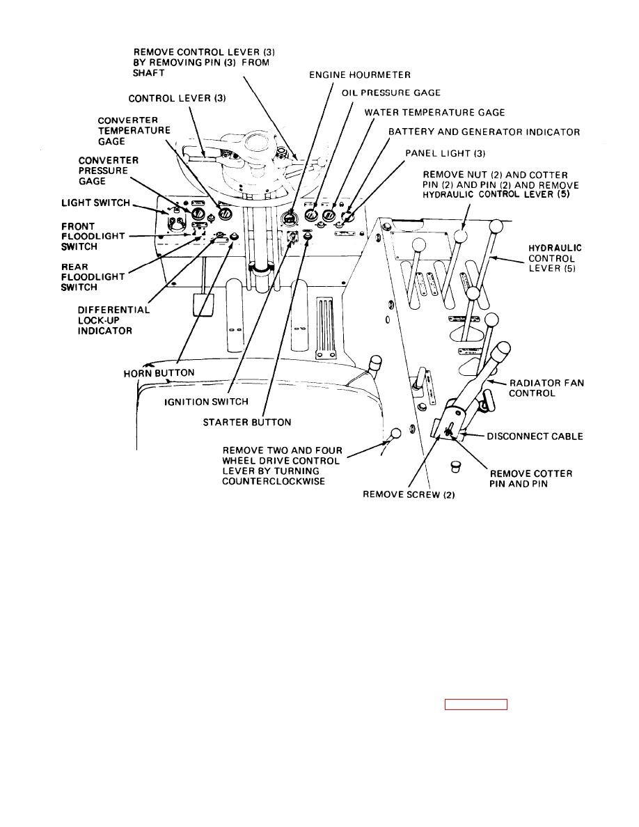
Figure 4-31. Controls and instruments, removal and installation. |
|
||
| ||||||||||
|
|
 TM10-3930-242-12
TAG AND DISCONNECT ELECTRICAL LEADS AND REMOVE MOUNTING
NOTE:
HARDWARE AS NECESSARY.
TA072399
on Athey Model ARTFT-6, S/N Range
F1468 thru F1596 and G1597 thru G1755
a. General. The differential lockout control is
(NSN 3930-00-419-5744). It is also used
located on the firewall of the driver's compartment.
on a limited number of Anthony Models
When the lockout pedal is pressed, oil (OE 10) or
MLTG-2, S/N 1098 thru 1159 and 1305
brake fluid HBA (MIL-H-13910) is forced to the
thru 1307 (NSN 3930-00-327-1475).
lockout mechanism, mounted on each differential.
This action insures that each pair of driving wheels
l o c k o u t control.
turn together.
c. Inspection and Service.
NOTE
(1) Inspect the rubber boot and hoses for cuts
Brake fluid HBA (MIL-H-13910) is used
|
|
Privacy Statement - Press Release - Copyright Information. - Contact Us |
