 |
|||
|
|
|||
|
|
|||
| ||||||||||
|
|
 (4) Add or remove shims at regulators A, B, C, and
(2) With control in neutral and engine running at
600 rpm, check transmission oil level. Fill as
D to increase or decrease pressure readings at
check ports 1, 2, 3, and 4. Add shims to
necessary.
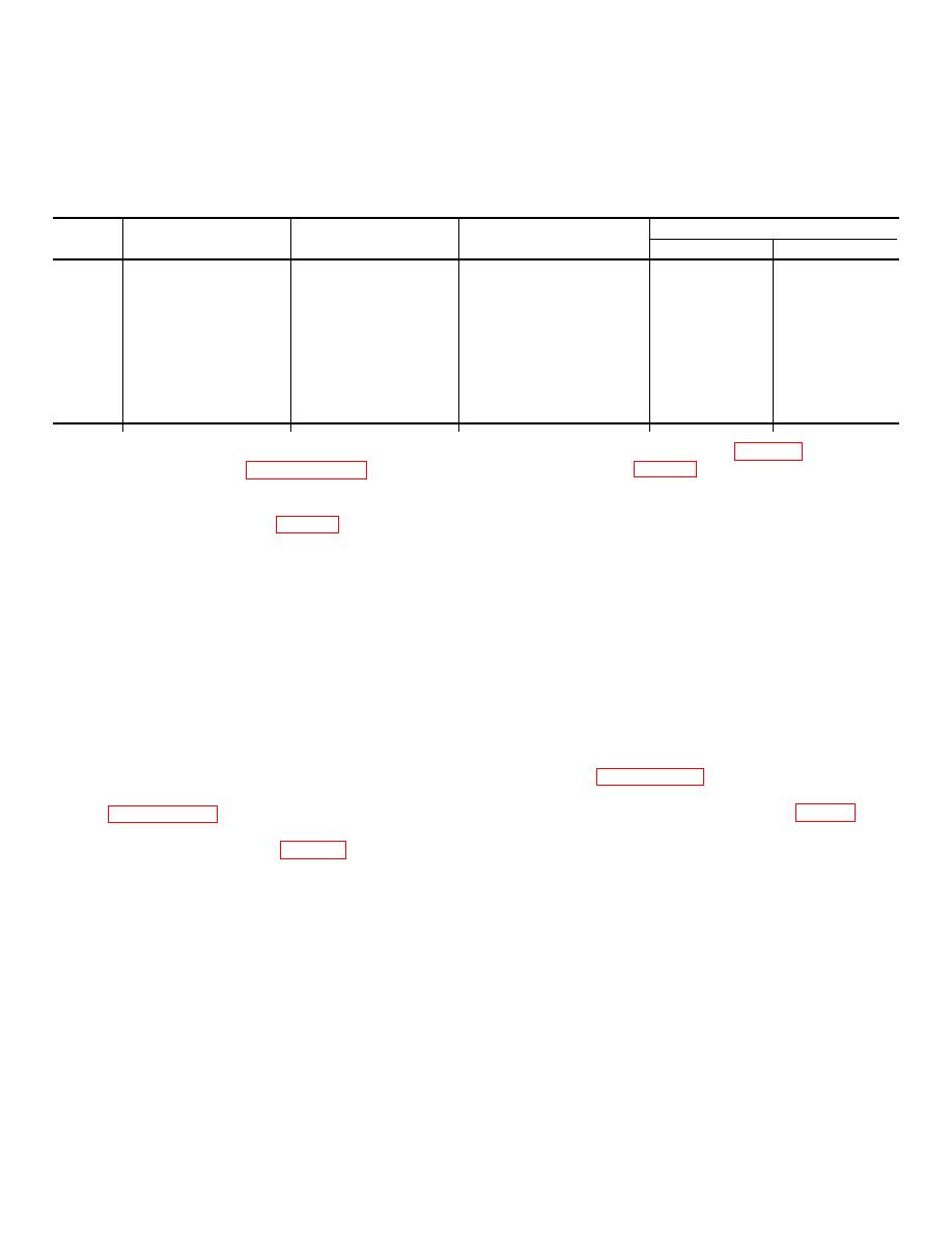
(3) Adjust pressures to the limits as shown in the
increase pre. sure; remove shims to decrease
pressure.
" ransmission Pressure Settings"below.
T
Transmission Pressure Settings
Check
Range
port
Regulator
Set to
Control position
600 rpm
2,400 rpm
1
A
130 to 140 psi
Neutral
110 psi
150 psi
Pump and Hi-Lo
at 1,500 rpm
2
B
85 to 95 psi
Neutral
30-85 psi
150 psi
Forward and Reverse
at 1,500 rpm
3
C
70-75 psi
Neutral
5-55 psi
75 psi
Converter In
at 2,400 rpm
4
D
Neutral
2 psi
45 psi
Converter Out
(4) Remove place bolts (14, fig. 32) and retainer
39. Ring Gear Assembly
plate (13, fig. 17). Separate cover (12) from
a. Removal.
Refer to paragraph 38b, steps (1)
cage assembly (3).
through (3).
(5) Remove gear (10) from cage assembly.
b. Disassembly.
(6) Remove thrust washers (9 and 11) from gear
(1) Remove snap ring (22, fig. 32) from ring gear
(10).
assembly (30).
(7) Remove pinion shafts (5), thrust washers (4 and
(2) Slide front cover (25) from gear assembly.
8), and pinion sets (6 and 7) from cage
(3) Remove snap ring (28) that retains bearing (29)
assembly.
to ring gear assembly shaft.
Note. The 18-tooth pinion set (6) meshes
(4) Using bearing puller remove bearing from shaft.
with the sun gear (10). The 19-tooth pinion set
(5) Remove needle bearing from shaft housing if
(7) measure with the ring gear assembly (30).
necessary.
c. Assembly.
Reverse procedures in b above.
c. Assembly. Reverse the procedures in b above.
Lubricate all parts before assembly.
d. Installation. Reverse the procedures in a above.
d. Installation. Reverse procedures in a above.
40. Planetary Carriage Assembly
41. Forward-and-Reverse Clutch Assembly
a. Removal.
a. Removal. Follow the procedures in steps (7)
(1) Remove transmission (par. 38a).
through (14), paragraph 38a.
(2) Remove planetary carriage assembly by
b. Disassembly.
following procedure in steps (1) through (4),
(1) Remove ring seals (11 and 12, fig. 40) from
forward drive shaft assembly (9).
b. Disassembly.
(2) Remove capscrews (21) that secure clutch
(1) Remove thrust washer (fig. 84) from carriage
assembly together.
assembly.
Caution: The clutch pack assembly will
(2) Remove safety wires that secure place bolts.
fall apart when removing the capscrews (21),
(3) Mark the cage Assembly and cover before
disassembly.
due to spring tension inside the pack, if care
is not exercised in removing capscrews.
AGO 7010A
38
|
|
Privacy Statement - Press Release - Copyright Information. - Contact Us |
