 |
|||
|
|
|||
|
|
|||
| ||||||||||
|
|
 TM 10-3930-673-34
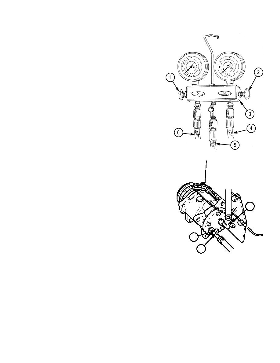
b. Manifold Gage Set Removal.
(1)
Loosen low pressure gage valve (1) and
high pressure gage valve (2) slowly,
allowing refrigerant to escape from
hoses (4) and (6) through hose (5).
(2)
Disconnect low pressure gage hose (5)
and high pressure gage hose (4) from
service valve ports (7) and (8).
(3)
Install two dust caps (9) on service valve
ports (7) and (8).
c. Discharging System.
(1)
Disconnect negative battery cable
(TM 10-3930-673-20).
(2)
Install manifold gage set (refer to task a.).
(3)
Insert center hose (5) of manifold gage
set (3) in a catch bottle or can.
NOTE
Do not allow refrigerant R-134 to
escape too quickly. Refrigerant oil
will escape.
When high pressure gage and low
pressure gage read "zero", the
8
discharging procedure is
complete.
(4)
Turn low pressure gage valve (1) and
high pressure gage valve (2)
9
counterclockwise slightly to permit
refrigerant to slowly escape through
7
center hose (5) until gages read "zero".
(5)
Measure any significant accumulation of
oil in discharge bottle and record for oil charging purposes.
(6)
Disconnect manifold gage set (refer to task b.).
15-7
|
|
Privacy Statement - Press Release - Copyright Information. - Contact Us |
