 |
|||
|
|
|||
|
Page Title:
REAR DIFFERENTIAL CARRIER ASSEMBLY REPLACEMENT/REPAIR/ ADJUSTMENT - continued |
|
||
| ||||||||||
|
|
 TM 10-3930-673-34
CAUTION
Install bearing caps in correct location to avoid thread damage by cross-threading
adjusting rings, when installed, or mismatching bearing caps.
(f)
Install bearing caps (10) over assembled bearing cups and bearing cones (16 and 17). Use
match marks made during disassembly to match original location of bearing caps.
(g)
Install screws (13) and washers (14) and tighten hand tight in bearing caps (10).
CAUTION
Install adjusting rings, using care not to cross-thread the rings or the caps. A plastic or
leather mallet can be used to align the rings and caps during installation. DO NOT force
adjusting rings; damage to threads may result.
(h)
Install adjusting rings (12) and tighten hand tight against each bearing cup (15).
(i)
Tighten screws (13) to 110 - 145 lb-ft (149.14 - 196.59 Nm).
f. Adjustment.
(1)
Adjust preload of differential
bearings (15, 16, and 17).
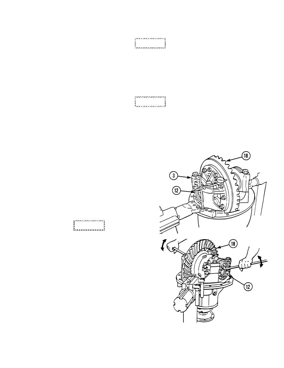
(a)
Attach a dial indicator on mounting
flange of differential carrier (3).
(b)
Adjust dial indicator so that plunger
is against back surface of ring
gear (18). Adjust dial indicator to
zero.
CAUTION
When turning bearing adjusting
TR00448
rings, always use a tool that engages
two or more opposite notches in the
ring. A large screwdriver can be
used for this purpose. Failure to
engage at least two notches could
cause damage to adjusting ring lugs.
(c)
Loosen bearing adjusting ring (12)
opposite ring gear (18) so that a
small amount of end play shows on
dial indicator. Move differential
assembly with ring gear left and
right with suitable pry bars while
reading dial indicator. DO NOT
allow pry bars to touch bearings (15,
16, and 17).
TR00452
9-25
|
|
Privacy Statement - Press Release - Copyright Information. - Contact Us |
