 |
|||
|
|
|||
|
Page Title:
REAR DIFFERENTIAL CARRIER ASSEMBLY REPLACEMENT/REPAIR/ ADJUSTMENT - continued |
|
||
| ||||||||||
|
|
 TM 10-3930-673-34
9-5. REAR DIFFERENTIAL CARRIER ASSEMBLY REPLACEMENT/REPAIR/
ADJUSTMENT (CONT)
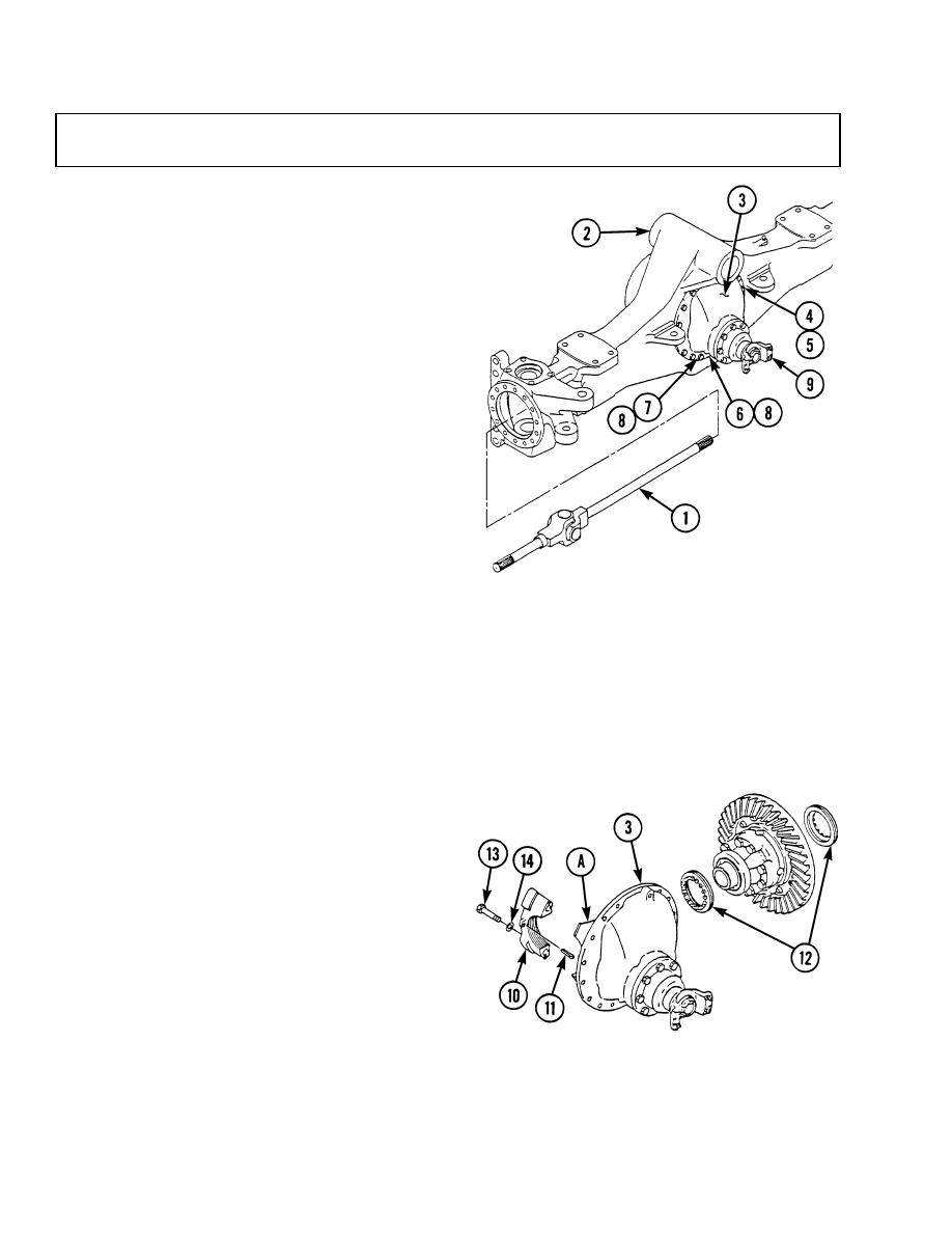
a. Removal.
(1)
Remove two axle shafts (1) from axle
housing (2).
(2)
Remove differential carrier (3) from
axle housing (2).
(a)
Carefully tip axle assembly so that
rear differential carrier (2) faces up.
NOTE
Screws from differential carrier to
axle housing are of three different
sizes. Note size, location and
quantity of screws when removing
for correct location during
replacement.
(b)
Remove 12 screws (4), washers (5),
two screws (6), two screws (7), and
four washers (8) from differential
carrier (3).
(c)
Use sling placed around bevel pinion behind companion yoke (9) to lift and support
differential carrier (3) during removal.
(d)
Use a leather or rubber mallet to loosen differential carrier (3) in axle housing (2).
(e)
Carefully remove differential carrier (3) from axle housing (2).
(f)
Place differential carrier (3) on suitable stand or bench with ring gear up and clamp securely.
b. Disassembly.
(1)
Remove differential and ring gear
assembly from differential
carrier (3).
(a)
Mark one carrier leg (A) and bearing
cap (10) for ease of assembly.
(b)
Remove two cotter pins (11) holding
bearing adjusting rings (12) in
position. Discard cotter pins.
(c)
Remove two screws (13) and
washers (14) from each of two
bearing caps (10).
(d)
Remove two bearing caps (10) and bearing adjusting rings (12) from differential carrier (3).
9-12
|
|
Privacy Statement - Press Release - Copyright Information. - Contact Us |