 |
|||
|
|
|||
|
Page Title:
Section II. FRONT AXLE MAINTENANCE PROCEDURES |
|
||
| ||||||||||
|
|
 TM 10-3930-673-34
8
Section II. FRONT AXLE MAINTENANCE PROCEDURES
This Task Covers:
a. Removal
c. Cleaning
e. Assembly
b. Disassembly
d. Inspection
f. Installation
INITIAL SETUP
Materials/Parts
Tools and Special Tools
Compound, Sealing (Item 14, Appendix B)
Tool Kit, General Mechanic's: Automotive
Oil, Lubricating, Gear (Item 29, Appendix B)
(Item 23, Appendix D)
Rags, Lint-free (Item 34, Appendix B)
Shop Equipment, Automotive Maintenance,
Tags (Item 55, Appendix B)
Common No. 2 Less Power
Locknut
(Item 17, Appendix D)
Lockwasher
Shop Equipment, Automotive maintenance and
Wood Blocks, 3 in. (76.2 mm)
Repair; Field Maintenance, Basic, Less Power
Container, 5 gal (18.93 l) capacity
(Item 18, Appendix D)
Steel Bar (minimum 1 in. [25.4 mm] diameter
Cap and Plug Set (Item 1, Appendix D)
and 6 ft [1.83 m] long)
Floor Jack, 10 ton (9071.84 kg) capacity
Jackstands (2) 40 in. (101.6 cm) height,
Personnel Required
3-1/2 ton (3175.14 kg) capacity
Two
Equipment Condition
Vehicle parked on level surface.
Parking brake set.
Rear wheels chocked.
a. Removal.
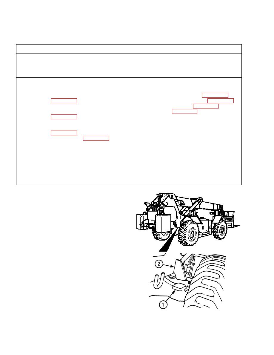
(1)
Place wood blocks (3 in. [76.2 mm]
thick) between frame pads (1) on
rear axle and frame tilt stop pads (2).
This will prevent frame from tilting
when removing front tilt cylinders.
(2)
Start engine and raise boom for
sufficient work clearance
TR00001
(TM 10-3930-673-10).
(3)
Disconnect parking brake cable
(TM 10-3930-673-20).
(4)
Remove front propeller shaft
(TM 10-3930-673-20).
(5)
Raise front of vehicle 8 in. (203.2
mm) off ground and support under
frame (TM 10-3930-673-20).
(6)
Remove frame tilt cylinder
TR00249
(TM 10-3930-673-20).
|
|
Privacy Statement - Press Release - Copyright Information. - Contact Us |