 |
|||
|
|
|||
|
Page Title:
Section II. ELECTRICAL SYSTEM MAINTENANCE PROCEDURES |
|
||
| ||||||||||
|
|
 TM 10-3930-673-34
Section II. ELECTRICAL SYSTEM MAINTENANCE PROCEDURES
6
6-3. ALTERNATOR REPAIR/TEST
This Task Covers:
a. Disassembly
c. Inspection
e. Assembly
b. Cleaning
d. Testing
INITIAL SETUP
Materials/Parts
Tools and Special Tools
Lubricant, Delco-Remy (Item 21, Appendix B)
Tool Kit, General Mechanic's: Automotive
Sandpaper (Item 37, Appendix B)
(Item 23, Appendix D)
Bearing Cap
Multimeter, Digital (Item 14, Appendix D)
Bushings (2)
Locknut
Equipment Condition
Alternator removed (TM 10-3930-673-20)
NOTE
Alternator is one of two different models
used on ATLAS vehicles. Although
configuration of a few components
between models is slightly different,
many are identical. This paragraph can be
used to repair/test either alternator.
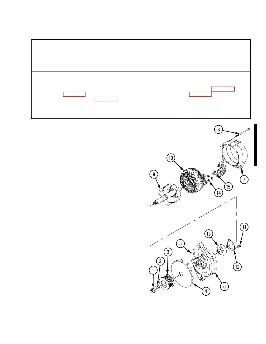
a. Disassembly.
(1)
Remove locknut (1), washer (2), pulley (3),
and fan (4) from alternator (5). Discard
locknut.
(2)
Separate front frame (6) from rear frame (7).
(a)
Remove four screws (8) from alternator
(5).
(b)
Separate front frame (6) and rotor
assembly (9) from rear frame (7) and
stator assembly (10).
(3)
Remove rotor assembly (9) from front frame
(6).
(a)
Use suitable press to remove bearing (13)
in front frame (6) from rotor assembly
(9).
(b)
Remove three screws (11), retainer plate
(12), and roller bearing (13) from front
frame (6).
(4)
Remove stator assembly (10) from rear
frame (7).
(a)
Remove three nuts (14) from studs (15).
TR01426
(b)
Remove stator assembly (10) from rear
frame (7).
|
|
Privacy Statement - Press Release - Copyright Information. - Contact Us |