 |
|||
|
|
|||
|
Page Title:
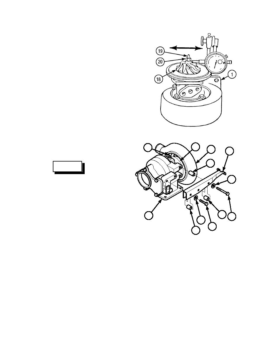
TURBOCHARGER ASSEMBLY REPAIR - continued |
|
||
| ||||||||||
|
|
 TM 10-3930-673-34
(27)
Measure radial clearance of shaft
and wheel (19).
(a)
Attach a dial indicator to turbine
housing (1). Adjust dial indicator
plunger so that plunger is against
end of impeller (18) between fins
and nut (20).
(b)
Set dial indicator to zero.
(c)
Move end of impeller (18) left and
right and read radial clearance on
dial indicator. If radial clearance is
less than 0.0128 in. (0.326 mm) or
greater than 0.018 in. (0.496 mm),
disassemble turbocharger, Steps (8)
through (25), and check for problem.
Replace defective parts and
TR01392
assemble, Steps (2) through (27).
(28)
Position compressor housing (13) on
14
15
bearing housing (14).
13
6
12
WARNING
Use care when installing snap and
10
retaining rings. Snap and retaining
rings are under spring tension and
can act as projectiles when released
and could cause severe eye injury.
(29)
Install retaining ring (15) on
11
compressor housing (13) and bearing
1
9
10
housing (14).
8
11
(30)
Install bracket (6), spacer (12), three
spacers (11), washers (10), and
TR01385
screws (8 and 9) on turbine
housing (1).
4-31
|
|
Privacy Statement - Press Release - Copyright Information. - Contact Us |
