 |
|||
|
|
|||
|
|
|||
| ||||||||||
|
|
 TM 10-3930-673-34
4
This Task Covers:
a. Disassembly
c. Inspection
b. Cleaning
d. Assembly
INITIAL SETUP
Materials/Parts
Tools and Special Tools
Engine Lubricating Oil (Item 27, Appendix B)
Tool Kit, General Mechanic's: Automotive
Locknuts (2)
(Item 23, Appendix D)
Locknut
Shop Equipment, Automotive Maintenance,
Retaining Ring
Common No. 2 Less Power
Retaining Ring
(Item 17, Appendix D)
Retaining Ring
Dial Indicator (Item 3, Appendix D)
Retaining Rings (2)
Retaining Rings (2)
Equipment Condition
Seal Ring
Turbocharger removed (TM 10-3930-673-20)
Seal Ring
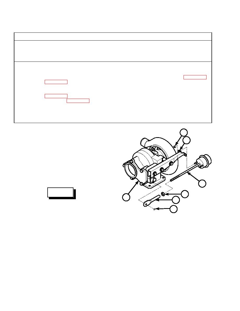
a. Disassembly.
4
(1)
Place turbocharger in a vise with
6
soft jaws and clamp by the turbine
housing (1) inlet flange.
NOTE
Note position and length of control
rod from boost capsule actuator for
aid in installation.
5
WARNING
7
1
3
Use care when removing snap and
retaining rings. Snap and retaining
2
rings are under spring tension and
TR01384
can act as projectiles when released
and could cause severe eye injury.
(2)
Remove retaining ring (2) from turbine housing (1) control lever.
(3)
Remove adjusting link (3) from turbine housing (1) control lever.
(4)
Remove two locknuts (4), boost capsule actuator (5), and adjusting link (3) from
bracket (6). Discard locknuts.
(5)
Loosen nut (7). Remove adjusting link (3) and nut from boost capsule actuator (5).
|
|
Privacy Statement - Press Release - Copyright Information. - Contact Us |
