 |
|||
|
|
|||
|
|
|||
| ||||||||||
|
|
 TM 10-3930-673-34
3-9. CRANKSHAFT MAIN BEARINGS REPLACEMENT (CONT)
TR01420
(j)
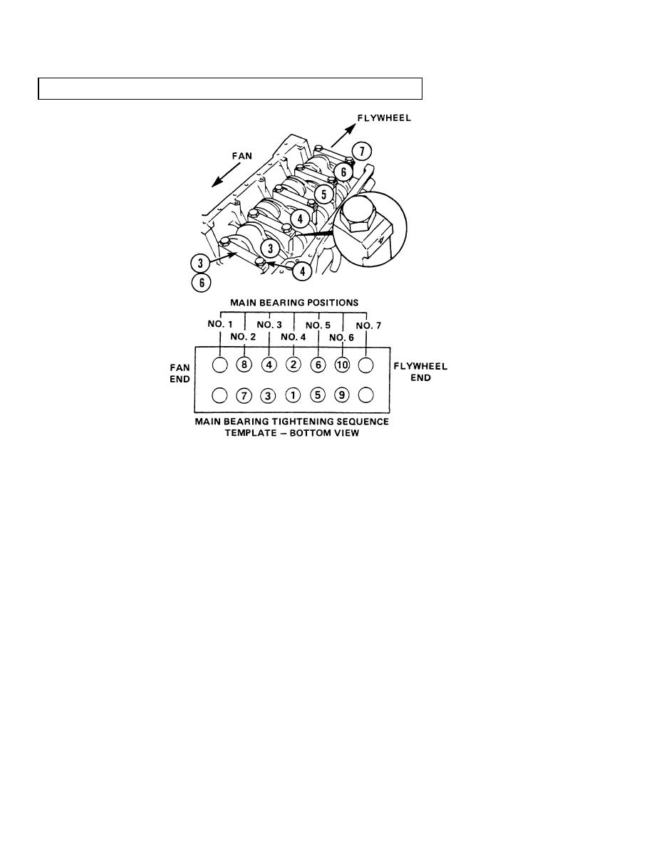
Apply a light coat of lubricating oil on threads of screws (4). Install lower bearing half (6),
bearing cap (3), and two screws. The bearing cap must be installed in the same position it was
removed from with number on bearing cap facing towards the oil cooler side of engine.
(k)
After each bearing and bearing cap (3) is installed, tighten screws (4) to 37 lb-ft (50.17 Nm).
Do not tighten screws to final torque value at this time.
(l)
Repeat Steps (a) through (j) for the other main bearings (5 and 6) in positions (2 through 5)
and thrust bearing (2) at position no. 6.
(m) Tighten screws (4) evenly, in the sequence shown, to 44 lb-ft (59.66 Nm).
(n)
Tighten screws (4) evenly again in the sequence shown to 88 lb-ft (119.31 Nm).
(o)
Tighten screws (4) evenly in the sequence shown to 129 lb-ft (174.90 Nm) final torque.
(2)
Check bearing clearance for main bearings at positions (2 through 6).
(a)
Remove two screws (4) and bearing cap (3) from main bearings positions (2, 3, 4, 5, or 6).
Remove one set of main bearings at a time.
(b)
Remove and measure plastigage. Main bearing clearance must not exceed 0.00474 in.
(0.12 mm). If bearing clearance exceeds the specified measurement, the appropriate oversize
bearing set must be installed.
3-78
|
|
Privacy Statement - Press Release - Copyright Information. - Contact Us |
