 |
|||
|
|
|||
|
|
|||
| ||||||||||
|
|
 TM 10-3930-673-34
(e)
Apply Lubriplate 105 to the inside surfaces of the upper and lower bearing halves (14 and 18)
and thrust bearing (19).
(f)
Slowly lower crankshaft into cylinder block. Be careful not to scratch the crankshaft journals.
(g)
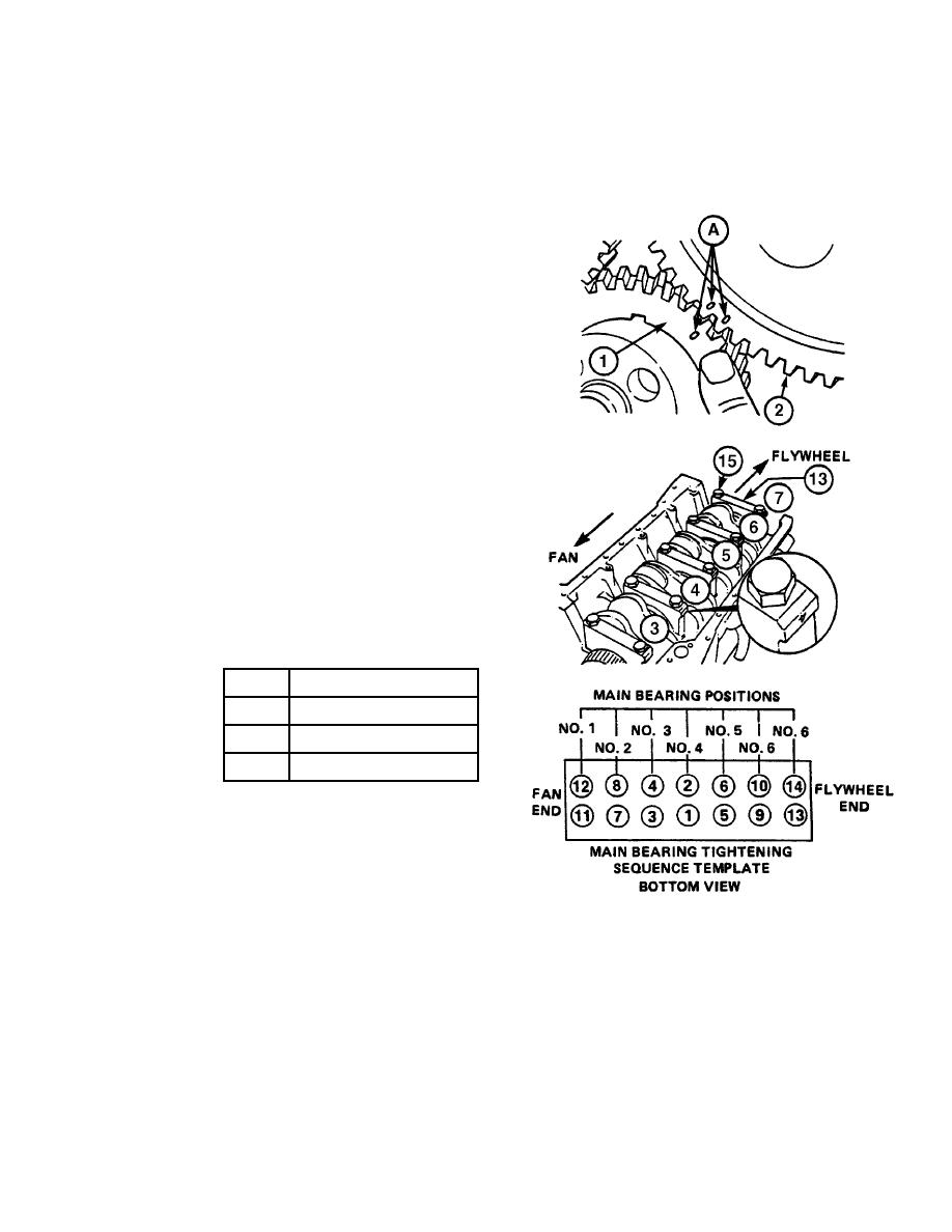
Check that the crankshaft gear (1)
to camshaft gear (2) timing marks
are aligned at point "A", then allow
crankshaft to firmly rest against the
upper bearing halves (18).
NOTE
The number on the bearing caps
must correspond to the numbers in
the cylinder block and they must be
towards the oil cooler side of the
engine.
(h)
Install seven bearing caps (13) and
14 screws (15). Tighten screws
finger tight.
(i)
The main bearing screws (15) must
be tightened evenly in a series of
three steps, and in the sequence
shown in this illustration. The
torque value for each step is shown
in this chart.
Step
Torque Value
1
44 lb-ft (59.66 Nm)
2
88 lb-ft (119.31 Nm)
3
129 lb-ft (174.90 Nm)
(4)
Check crankshaft (16) end play.
NOTE
End play is controlled by the
dimensions of the thrust bearing
TR01175
and crankshaft journal at the no. 6
main bearing position.
(a)
Measure crankshaft (16) end play using a dial indicator as shown in this illustration.
(b)
Push crankshaft (16) forward, then toward rear of engine. With a new thrust bearing, end
play limits must not exceed 0.005 - 0.010 in. (0.13 - 0.25 mm).
(c)
If end play measurement is greater than 0.010 in. (0.25 mm), install a larger size thrust
bearing (19).
3-67
|
|
Privacy Statement - Press Release - Copyright Information. - Contact Us |