 |
|||
|
|
|||
|
Page Title:
Adjust Accumulator Charging Pressure |
|
||
| ||||||||||
|
|
 TM 10-3930-673-20-2
CAUTION
Brake system and hydraulic accumulator must be bled as soon as brake control valve is installed. If not
done, air in system may not allow brakes to release and may cause severe brake system damage.
(f)
Bleed hydraulic accumulator (Para 12-8).
(g)
Bleed brake system (Para 12-5).
c. Adjust Accumulator Charging Pressure.
NOTE
Accumulator charging pressure is
adjusted at brake control valve.
(1)
Pump brake pedal
(TM 10-3930-673-10) to relieve service brake
hydraulic accumulator pressure.
With engine OFF (TM 10-3930-673-10), pump
brake pedal (TM 10-3930-673-10) until no power
assistance is felt through pedal. This will require
approximately 20 depressions of brake pedal.
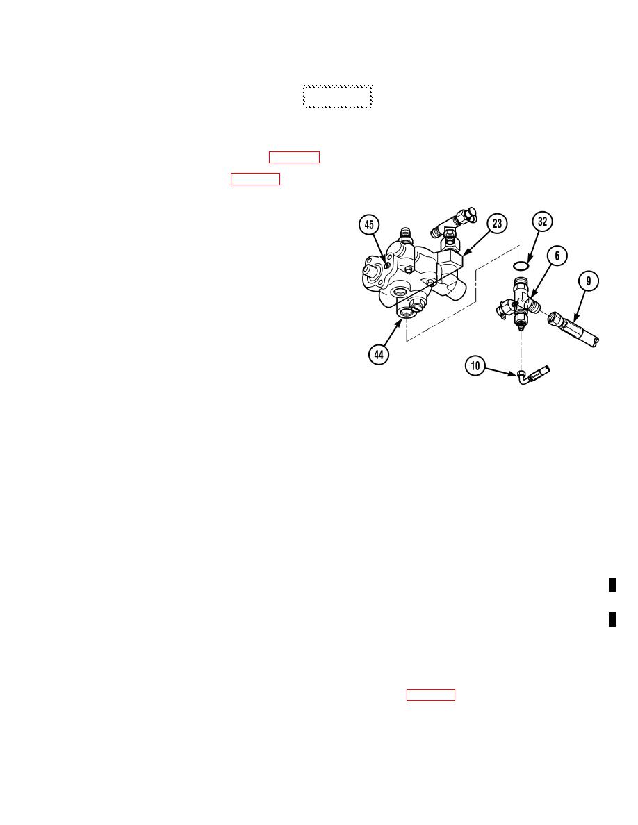
TR00598
(2)
Remove hoses (9 and 10), tee (6) and
preformed packing (32) from service brake
control valve (23).
(3)
Install pressure gauge in accumulator port (44) on service brake control valve (23).
NOTE
Note pressure gauge reading when click is heard in Step (4) below.
(4)
Start engine (TM 10-3930-673-10) and listen for click of accumulator charging valve inside service brake
control valve (23).
(5)
If necessary, adjust accumulator charging pressure.
(a)
If pressure is less than 1700-1800 psi (11721 to 12411 kPa) - 2350 to 2450 psi (16203 to 16892 kPa) fully
charged at time click is heard, turn adjusting plug (45) on valve (23) clockwise until pressure is within
specifications.
(b)
If pressure is greater than 1700-1800 psi (11721 to 12411 kPa) - 2350 to 2450 psi (16203 to 16892 kPa) fully
charged at time click is heard, turn adjusting plug (45) on valve (23) counterclockwise until pressure is
within specifications.
(6)
Remove pressure gauge from accumulator port (44) on service brake control valve (23).
NOTE
Follow-on Maintenance: Bleed brake system (Para 12-5).
END OF TASK
|
|
Privacy Statement - Press Release - Copyright Information. - Contact Us |