 |
|||
|
|
|||
|
Page Title:
BRAKE HYDRAULIC PRESSURE SWITCH TEST/REPLACEMENT |
|
||
| ||||||||||
|
|
 TM 10-3930-673-20-2
6
This Task Covers:
a. Test
b. Removal
c. Installation
INITIAL SETUP
Equipment Condition
Tools and Special Tools
Negative battery cable disconnected (Para 8-44)
Tool Kit, General Mechanic's: Automotive
(Item 18, Appendix F)
Materials/Parts
Compound, Sealing (Item 32, Appendix C)
Test Equipment
Varnish, Anti-fungus (Item 42, Appendix C)
Ohmmeter (Item 10, Appendix F)
Container
a. Test.
(1)
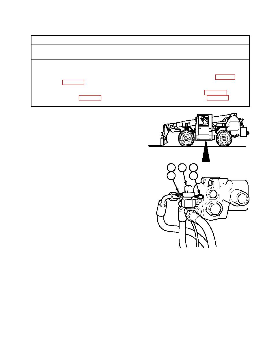
Tag, mark, and remove two connectors (1)
from connectors (2) on brake hydraulic
pressure switch (3).
(2)
Connect ohmmeter across connectors (2) on
brake hydraulic pressure switch (3).
TR00004
(3)
Test brake hydraulic pressure switch (3) for
continuity.
1
1
3
2
2
(a)
With engine OFF, pump brake pedal a
minimum of 20 times to exhaust stored
brake system pressure.
(b)
Observe ohmmeter. Ohmmeter should
show continuity.
(c)
Start vehicle and allow brake system
accumulator to charge.
(d)
Observe ohmmeter. Ohmmeter should
show no continuity.
(e)
Turn engine OFF.
TR00320
(f)
If brake hydraulic pressure switch (3)
does not pass continuity test, brake
hydraulic system must be repaired.
(g)
If brake hydraulic pressures are within normal range, brake hydraulic pressure switch (3) must be replaced
as described in Removal and Installation sections below.
|
|
Privacy Statement - Press Release - Copyright Information. - Contact Us |