 |
|||
|
|
|||
|
Page Title:
ELECTRIC JOYSTICK CONTROL DOES NOT OPERATE - continued |
|
||
| ||||||||||
|
|
 TM 10-3930-673-20-1
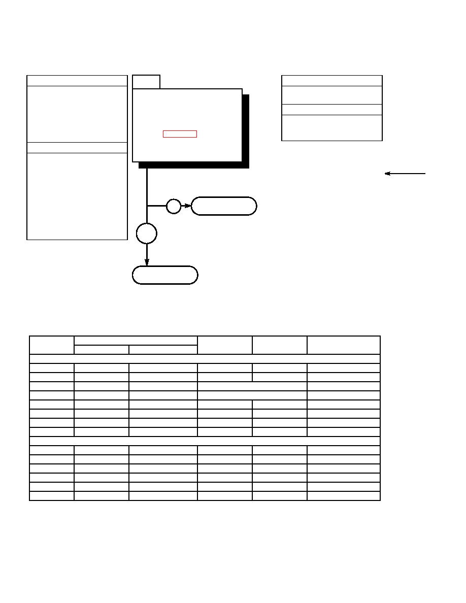
33. ELECTRIC JOYSTICK CONTROL DOES NOT OPERATE (CONT).
5
KNOWN INFO
TEST OPTIONS
Hydraulic system OK.
Voltage test.
Is voltage present at
Auto-leveler OK.
STE/ICE-R #89.
numbered connector in
Joystick OK.
REASON FOR QUESTION
Connector J3 OK.
electrical junction box for
This question eliminates possible
Connector P3 OK.
specified wire/function as
problems and determines where
Connector J1 OK.
listed in Table 2-6?
troubleshooting continues.
Connector P1 OK.
POSSIBLE PROBLEMS
Connector J4 faulty.
Connector P4 faulty.
Wire 51 faulty.
Wire 52 faulty.
Wire 53 faulty.
Wire 54 faulty.
Go to Step 6 of this
Wire 55 faulty.
NO
fault.
Wire 56 faulty.
Fork leveler mode switch faulty.
Wire 57 faulty.
YES
Wire 58 faulty.
Go to Step 7 of this
fault.
Electrical Junction Box Connector
Boom
In
Out
Connector
Main Connector
Function
Wire
Button Out
2
TB1-16
TB1-32
Ground
51
TB2-14
TB2-32, 31, 30, and 29
J4-K
P4-K
J1-27
P1-27
Attachment Ground
53
TB1-4
TB1-20
Fork Leveler Switch
Fork Tilt Up
54
TB1-5
TB1-21
Fork Leveler Switch
Fork Tilt Down
55
TB1-7
TB1-23
J4-X
P4-X
J1-31
P1-31
Attachment Raise
56
TB1-9
TB1-25
J4-L
P4-L
J1-32
P1-32
Attachment Lower
57
TB1-15
TB1-31
J4-M
P4-M
J1-33
P1-33
Fork Tilt Up
58
TB1-11
TB-127
J4-S
P4-S
J1-34
P1-34
Fork Tilt Down
Button In
2
TB1-16
TB1-32
Ground
52
TB2-14
TB2-3, 17, 18, and 19
J4-H
P4-H
J1-28
P1-28
Attachment Ground
53
TB1-4
TB1-20
J4-J
P4-J
J1-29
P1-29
Left Fork In
54
TB1-5
TB1-21
J4-A
P4-A
J1-30
P1-30
Left Fork Out
55
TB1-7
TB1-23
J4-X
P4-X
J1-31
P1-31
Right Fork In
56
TB1-9
TB1-25
J4-L
P4-L
J1-32
P1-32
Right Fork Out
2-496
|
|
Privacy Statement - Press Release - Copyright Information. - Contact Us |