 |
|||
|
|
|||
|
Page Title:
ELECTRIC JOYSTICK CONTROL DOES NOT OPERATE - continued |
|
||
| ||||||||||
|
|
 TM 10-3930-673-20-1
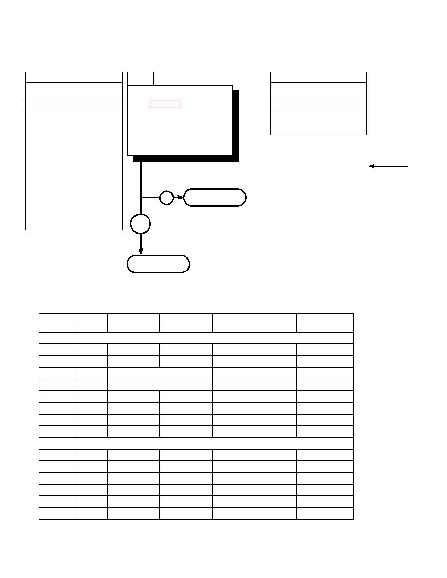
33. ELECTRIC JOYSTICK CONTROL DOES NOT OPERATE (CONT).
3
KNOWN INFO
TEST OPTIONS
Hydraulic system OK.
Voltage test.
Is voltage present at specified
Auto-leveler OK.
STE/ICE-R #89.
pin in Table 2-5 for
POSSIBLE PROBLEMS
REASON FOR QUESTION
appropriate function?
Joystick faulty.
This question eliminates possible
Connector J3 faulty.
problems and determines where
Connector P3 faulty.
troubleshooting continues.
Connector J1 faulty.
Connector P1 faulty.
Connector J4 faulty.
Connector P4 faulty.
Wire 51 faulty.
Wire 52 faulty.
Wire 53 faulty.
Wire 54 faulty.
Go to Step 4 of this
Wire 55 faulty.
NO
fault.
Wire 56 faulty.
Fork leveler mode switch faulty.
Wire 57 faulty.
YES
Wire 58 faulty.
Go to Step 5 of this
fault.
Joystick
Main
Boom
Joystick Terminal Board
Connector
Wire
Connector
Connector
and Pin
Function
Button Out
P3-C
2
J2-2
P2-2
TB1-C, TB2-__, and TB-3__
Ground
P3-E
51
J1-27
P1-27
J4-K
P4-K
TB1-B
Fork Ground
P3-G
53
Fork Leveler Switch
TB2-A
Fork Tilt Up
P3-D
54
Fork Leveler Switch
TB2-B
Fork Tilt Down
P3-J
55
J1-31
P1-31
J4-X
P4-X
TB3-A
Attachment Raise
P3-F
56
J1-32
P1-32
J4-L
P4-L
TB3-B
Attachment Lower
57
J1-33
P1-32
J4-M
P4-M
Fork Tilt Up
58
J1-34
P1-34
J4-S
P4-S
Fork Tilt Down
Button In
P3-C
2
J2-2
P2-2
TB1-C, TB2-__, and TB3-__
Ground
P3-H
52
J1-28
P1-28
J4-H
P4-H
TB2-A
Attachment Ground
P3-G
53
J1-29
P1-29
J4-J
P4-J
TB2-A
Left Fork In
P3-D
54
J1-30
P1-30
J4-A
P4-A
TB2-B
Left Fork Out
P3-J
55
J1-31
P1-31
J4-X
P4-X
TB3-A
Right Fork In
P3-F
56
J1-32
P1-32
J4-L
P4-L
TB3-B
Right Fork Out
2-492
|
|
Privacy Statement - Press Release - Copyright Information. - Contact Us |