 |
|||
|
|
|||
|
Page Title:
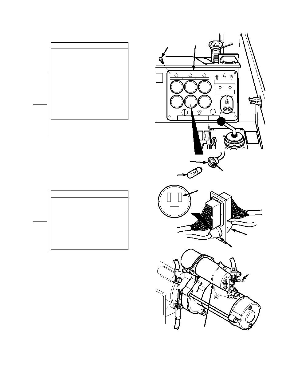
INSTRUMENT PANEL GAGE LIGHTS DO NOT OPERATE - continued |
|
||
| ||||||||||
|
|
 TM 10-3930-673-20-1
INSPRUMENT
T
ANEL
SCREW
VISUAL INSPECTION
(1) Lift instrument panel out to remove
gage light from gage.
(a) If grounding fins fit properly,
replace bulb (Para 8-6).
(b) If grounding fins are not fitting
properly, adjust by performing
Steps (2) and (3) below.
(2) Remove bulb from socket.
(3) Use small common screwdriver to
adjust ground fins inward or outward
for proper fit.
(4) Connect female to male connector.
(5) Install gage light into gage.
(6) Install instrument panel and four
screws.
S LIGHT
OCKET
GROUNDING
F
BULB
INS
P2-1
CONTINUITY TEST
(1) Set multimeter to ohms.
(2) Disconnect connector J2 from
connector P2.
(3) Connect multimeter positive lead (+) to
wire 9 at starter motor solenoid.
CONNECTOR P2
(4) Connect multimeter negative lead () to
connector P2-1.
(a) If continuity is present, go to
CONNECTOR
J
Step 16 of this fault.
2
(b) If continuity is not present, repair
wire 9 or connector P2 (Para 8-49).
CONNECTOR P2
WIRE 9
STARTER SOLENOID
TR01150
2-117
|
|
Privacy Statement - Press Release - Copyright Information. - Contact Us |
