 |
|||
|
|
|||
|
Page Title:
INSTRUMENT PANEL GAGE LIGHTS DO NOT OPERATE - continued |
|
||
| ||||||||||
|
|
 TM 10-3930-673-20-1
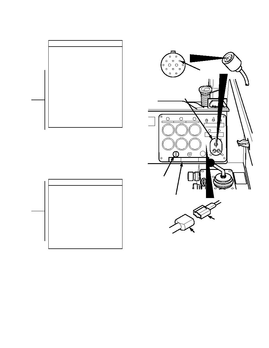
CONTINUITY TEST
(1) Remove connector J3 from blackout
light switch.
(2) Disconnect female from male
connector on wire 13.
(3) Set multimeter to ohms.
J3-B
(4) Connect multimeter positive lead (+) to
connector J3-B where wire 13
CONNECTOR J3
connects.
(5) Connect multimeter negative lead () to
female connector of wire 13.
BLACKOUT
(a) If continuity is present, replace
LIGHT SWITCH
blackout light switch (Para 8-13).
(b) If continuity is not present, repair
wire 13 (Para 8-48).
(6) Connect connector J3 to blackout light
switch.
(7) Connect female to male connector of
wire 13.
ENGINE
CONTINUITY TEST
START
SWITCH
(1) Disconnect female from male
connector on wire 13.
INSTRUMENT
(2) Set multimeter to ohms.
(3) Connect multimeter positive lead (+) to
PANEL
socket center conductor where wire 13
connects.
FEMALE
(4) Connect multimeter negative lead () to
CONNECTOR
male connector of wire 13.
(a) If continuity is present, go to
WIRE 13
Step 14 of this fault.
(b) If continuity is not present, replace
MALE
gage light socket (Para 8-6).
CONNECTOR
(5) Connect female to male connector of
WIRE 13
wire 13.
TR01149
2-115
|
|
Privacy Statement - Press Release - Copyright Information. - Contact Us |
