 |
|||
|
|
|||
|
|
|||
| ||||||||||
|
|
 TM 10-3930-660-24-2
MAIN CONTROL VALVE ASSEMBLY MAINTENANCE - CONTINUED
0303 00
DISASSEMBLY - CONTINUED
19.
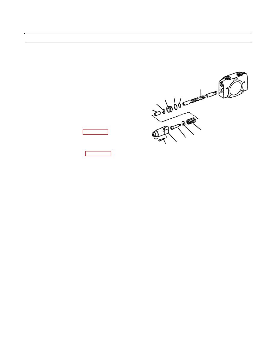
Remove two cap screws (57) from two spool caps (58).
20.
Remove two socket head shoulder screws (59), flat-
washers (60), springs (61), spacers (62) and flatwash-
ers (63).
67,68
65 66
21.
Remove two retainers (64) and O-rings (65 and 66).
64
Discard O-rings.
63
62
22.
Remove two spools (67 and 68).
CLEANING
61
See Cleaning instructions (WP 0316 00).
60
59
INSPECTION
58
57
409-1378
See Inspection instructions (WP 0317 00).
ASSEMBLY
NOTE
Wipe all sealing surfaces on main control valve clean and dry. Apply film of clean lubricating oil to all seals
as they are installed.
1.
Install two spools (67 and 68).
2.
Install new O-rings (65 and 66) on two retainers (64).
3.
Install two retainers (64), flatwashers (63), spacers (62), springs (61), flatwashers (60) and socket head shoulder screws
(59).
4.
Install two spool caps (58) and cap screws (57).
5.
If removal of plug assembly (56) was necessary, install it in housing section (43).
6.
Install two new O-rings (55) on spool caps (54).
7.
Install two spool caps (54) and capscrews (53).
8.
If removal of plug (52) was necessary, install it in inlet housing (51).
9.
Install three new O-rings (46) in housing sections (42, 43 and 51).
10.
Install two poppets (45) and springs (44).
11.
Use match lines on housing sections (41, 42, 43 and 51) and install them in proper order on tie rods (49 and 50).
12.
Install two nuts (47), one nut (48), two nuts (39) and one nut (40) on tie rods (49 and 50).
13.
Torque nuts (40 and 48) to 74 lb-ft (100 Nm) torque nuts (39 and 47) to 48 lb-ft (65 Nm).
0303 00-3
|
|
Privacy Statement - Press Release - Copyright Information. - Contact Us |