 |
|||
|
|
|||
|
|
|||
| ||||||||||
|
|
 TM 10-3930-660-24-2
TURBOCHARGER ASSEMBLY REPAIR (165 HP) - CONTINUED
0282 00
ASSEMBLY - CONTINUED
37.
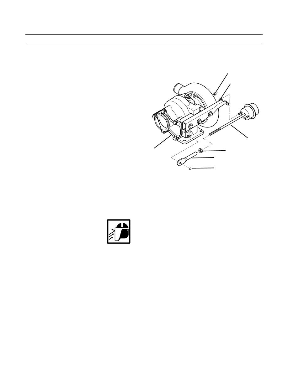
Install nut (7) and adjusting link (3) on boost capsule actuator (5).
38.
Install boost capsule actuator (5) and two locknuts (4)
4
on bracket (6). Torque locknuts to 40 lb-in. (54 Nm).
6
39.
Install turbocharger (WP 0026 00).
40.
Measure boost capsule actuator (5) travel. Specified
travel should be 0.013 to 0.050 in. (0.33-1.27 mm).
41.
Attach a dial indicator to the turbine housing (1).
42.
Set dial indicator to zero.
43.
Apply 27.7 psi (191 kPa) regulated air pressure to
boost capsule actuator (5).
44.
Measure boost capsule actuator (5) travel. If travel is
less than 0.013 in. (0.33 mm) or greater than 0.050 in.
5
(1.27 mm) replace boost capsule actuator.
7
1
3
2
409-1819
TR01384
45.
Position turbine housing (1) lever towards boost capsule actuator (5).
CAUTION
Do not force alignment of boost capsule actuator or adjusting link to avoid causing component damage.
46.
Adjust the adjusting link (3) length to where adjusting link aligns with turbine housing (1) lever.
WARNING
Use care when installing snap and retaining rings. Snap and retaining rings are under spring tension and can
act as projectiles when released and could cause severe eye injury.
47.
Install adjusting link (3) and retaining ring (2) on turbine housing (1) lever.
48.
Disconnect regulated air pressure from boost capsule actuator (5).
END OF WORK PACKAGE
0282 00-12
|
|
Privacy Statement - Press Release - Copyright Information. - Contact Us |
