 |
|||
|
|
|||
|
|
|||
| ||||||||||
|
|
 TM 10-3930-660-24-2
PISTON PUMP MAINTENANCE - CONTINUED
0256 00
ASSEMBLY - CONTINUED
31.
Use tapered feeler gauge to measure opening between valve block (3) and housing (6). Four measurements should be
obtained equidistant around unit. Average four readings by adding them together and dividing by 4. Calculate thickness
of shaft bearing spacer as shown in the following example:
+ 0.150 in. (3.81 mm) = measured thickness of bearing spacer
- 0.027 in. (0.68 mm) = average gap (estimated)
+0.003 in. (0.076 mm) +
0.001 in. (0.025 mm) = preload setting
+0.020 in. (0.508 mm) = compressed thickness of gasket
0.146 + 0.001 in. = required bearing spacer thickness to provide a 0.003 + 0.001 in. bearing preload
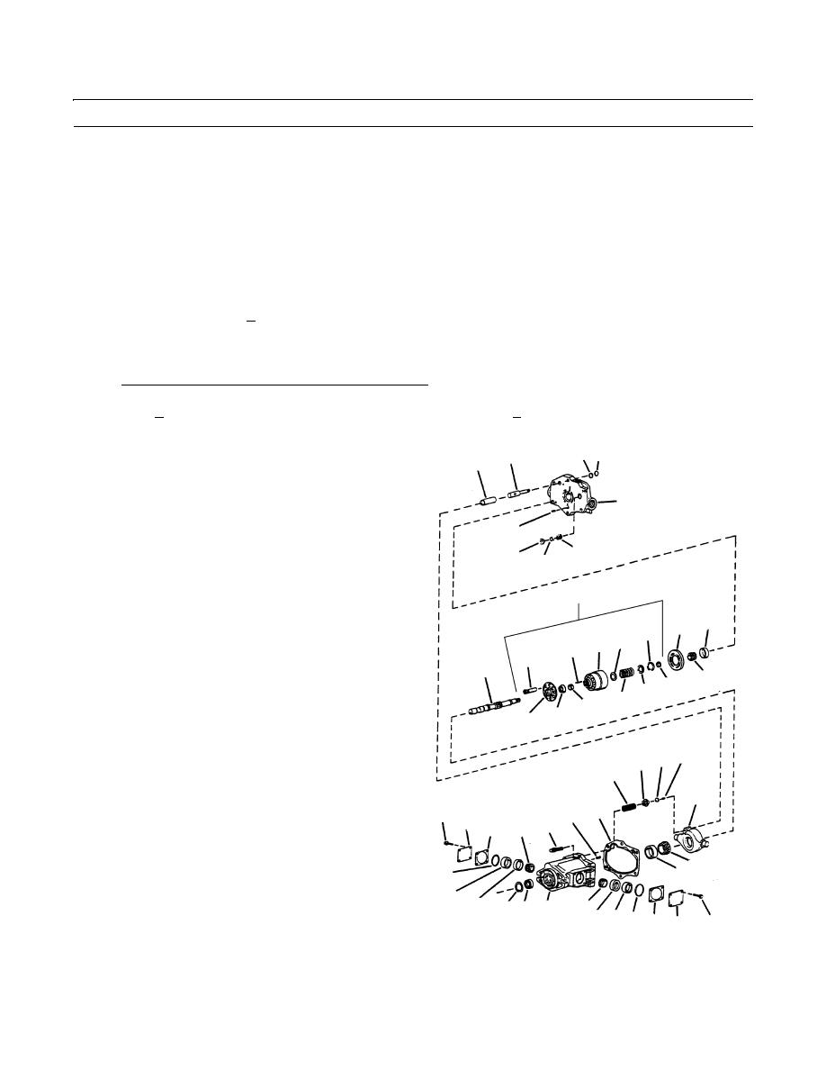
32.
Remove the six mounting screws (8), then remove
47 46
8
7
housing (6) from valve block (3).
33.
Remove bearing (13) and thickest bearing spacer (14)
3
from shaft (15).
34.
Locate bearing spacer (14) in kit with dimensions cal-
12
culated in step 35 above. Place spacer (14) next to the
44
new bearing (13) on shaft (15), with chamfer of spacer
42
43
facing the shaft shoulder. Use the original spacer (14)
and bearing (13) if preload is not required. Set aside
18
until final assembly is performed.
48
11
21
17 23
16
23
15
13
22 14
20
25
24
19
34 36 37
35
26
49 10
28 29
9
27
31
38
39
32
33
30
31
40 41 6
30 33 32 27 29
28
409-1473
0256 00-10
|
|
Privacy Statement - Press Release - Copyright Information. - Contact Us |
