 |
|||
|
|
|||
|
Page Title:
TESTING AND ADJUSTING OF JOYSTICK "THRESHOLD" AND "MAX OUT" SETTINGS |
|
||
| ||||||||||
|
|
 TM 10-3930-660-24-2
ELECTRIC JOYSTICK MAINTENANCE - CONTINUED
0235 00
TESTING AND ADJUSTING OF JOYSTICK "THRESHOLD" AND "MAX OUT" SETTINGS
1.
Install electric joystick (WP 0078 00).
WARNING
Take necessary precautions to ensure ade-
quate personal safety while testing electri-
cal leads when electrical power is
connected. Failure to do so can result in
injury or death.
2.
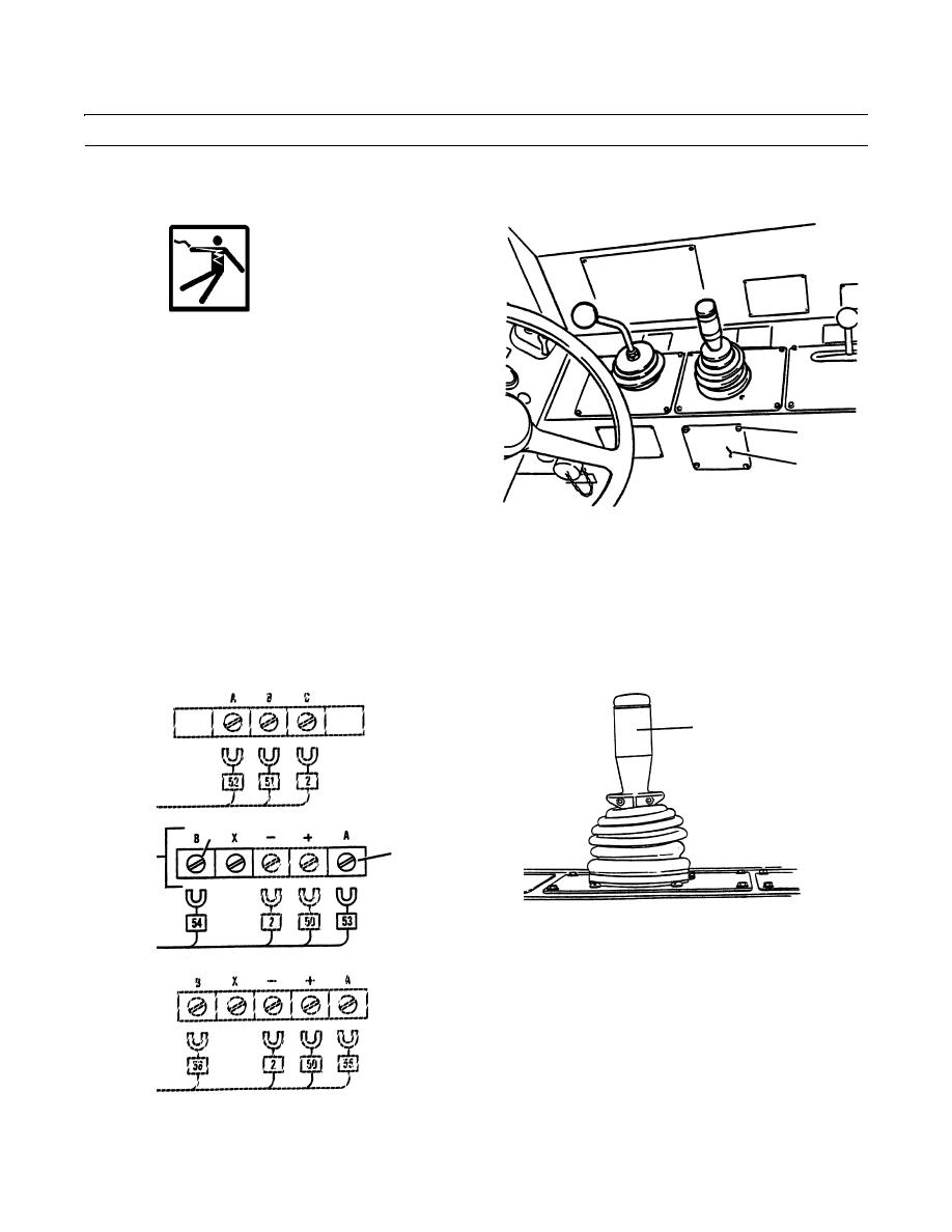
Remove four capscrews (23) and plate (24).
23
3.
Measure current flow to upper circuit board (21). If
24
necessary, adjust threshold and max out controls.
409-1129
4.
Loosen screw (25) at terminal A of upper circuit board (21) and disconnect electrical lead no. 53.
5.
Connect positive (+) lead of suitable ammeter to terminal A of upper circuit board (21).
6.
Connect negative (-) lead of ammeter to disconnected electrical lead no. 53.
7.
Turn starter switch to the RUN position but do not start the engine (TM 10-3930-660-10).
8.
Slowly move joystick handle (7) to the left until indicator light (26) just comes on. Ammeter reading should be between
300 and 340 mA.
7
29
25
21
409-1131
409-1130
0235 00-4
|
|
Privacy Statement - Press Release - Copyright Information. - Contact Us |